Motor protection and control
Manual motor starters,
A9 ... A300 contactors
and overload relays
Main catalog
Motor protection and control
Manual motor starters,
A9 ... A300 contactors
and overload relays
Main catalog

Motor rated operational powers and currents
The currents given below concern standard three-phase four-pole cage motors (1500 r.p.m. at 50 Hz 1800 r.p.m. at 60 Hz).
These values are given for guidance and may vary according to the motor manufacturer and depending on the number of poles.
IEC
Motor nominal current:
standardized values in blue colour
(according to IEC 60947-4-1 Annex G)
Motor
power
220 V
230 V
240 V 380 V
400 V
415 V 440 V
500 V
660 V
690 V
kW
A
A
A
A
A
A
A
A
A
A
0.06
0.37
0.35
0.34
0.21
0.2
0.19
0.18
0.16
0.13
0.12
0.09
0.54
0.52
0.50
0.32
0.3
0.29
0.26
0.24
0.18
0.17
0.12
0.73
0.7
0.67
0.46
0.44
0.42
0.39
0.32
0.24
0.23
0.18
1
1
1
0.63
0.6
0.58
0.53
0.48
0.37
0.35
0.25
1.6
1.5
1.4
0.9
0.85
0.82
0.74
0.68
0.51
0.49
0.37
2.0
1.9
1.8
1.2
1.1
1.1
1
0.88
0.67
0.64
0.55
2.7
2.6
2.5
1.6
1.5
1.4
1.3
1.2
0.91
0.87
0.75
3.5
3.3
3.2
2.0
1.9
1.8
1.7
1.5
1.15
1.1
1.1
4.9
4.7
4.5
2.8
2.7
2.6
2.4
2.2
1.7
1.6
1.5
6.6
6.3
6
3.8
3.6
3.5
3.2
2.9
2.2
2.1
2.2
8.9
8.5
8.1
5.2
4.9
4.7
4.3
3.9
2.9
2.8
3
11.8
11.3
10.8
6.8
6.5
6.3
5.7
5.2
4
3.8
4
15.7
15
14.4
8.9
8.5
8.2
7.4
6.8
5.1
4.9
5.5
20.9
20
19.2
12.1
11.5
11.1
10.1
9.2
7
6.7
7.5
28.2
27
25.9
16.3
15.5
14.9
13.6
12.4
9.3
8.9
11
39.7
38
36.4
23.2
22
21.2
19.3
17.6
13.4
12.8
15
53.3
51
48.9
30.5
29
28
25.4
23
17.8
17
18.5
63.8
61
58.5
36.8
35
33.7
30.7
28
22
21
22
75.3
72
69
43.2
41
39.5
35.9
33
25.1
24
30
100
96
92
57.9
55
53
48.2
44
33.5
32
37
120
115
110
69
66
64
58
53
40.8
39
45
146
140
134
84
80
77
70
64
49.1
47
55
177
169
162
102
97
93
85
78
59.6
57
75
240
230
220
139
132
127
116
106
81
77
90
291
278
266
168
160
154
140
128
97
93
110
355
340
326
205
195
188
171
156
118
113
132
418
400
383
242
230
222
202
184
140
134
160
509
487
467
295
280
270
245
224
169
162
200
637
609
584
368
350
337
307
280
212
203
250
782
748
717
453
430
414
377
344
261
250
315
983
940
901
568
540
520
473
432
327
313
355
1109
1061
1017 642
610
588
535
488
370
354
400
1255
1200
1150 726
690
665
605
552
418
400
500
1545
1478
1416 895
850
819
745
680
515
493
560
1727
1652
1583 1000
950
916
832
760
576
551
630
1928
1844
1767 1116
1060
1022 929
848
643
615
710
2164
2070
1984 1253
1190
1147 1043
952
721
690
800
2446
2340
2243 1417
1346
1297 1179
1076
815
780
900
2760
2640
2530 1598
1518
1463 1330
1214
920
880
1000
3042
2910
2789 1761
1673
1613 1466
1339
1014
970
UL / CSA
Motor nominal current:
standardized values
(according to IEC 60947-4-1 Annex G and UL 508)
Motor
power
208 V
220-240 V
380-415 V
440-480 V
550-600 V
hp
A
A
A
A
A
1/2
2.4
2.2
1.3
1.1
0.9
3/4
3.5
3.2
1.8
1.6
1.3
1
4.6
4.2
2.3
2.1
1.7
1-1/2
6.6
6
3.3
3
2.4
2
7.5
6.8
4.3
3.4
2.7
3
10.6
9.6
6.1
4.8
3.9
5
16.7
15.2
9.7
7.6
6.1
7-1/2
24.2
22
14
11
9
10
30.8
28
18
14
11
15
46.2
42
27
21
17
20
59.4
54
34
27
22
25
74.8
68
44
34
27
30
88
80
51
40
32
40
114
104
66
52
41
50
143
130
83
65
52
60
169
154
103
77
62
75
211
192
128
96
77
100
273
248
165
124
99
125
343
312
208
156
125
150
396
360
240
180
144
200
528
480
320
240
192
250
–
604
403
302
242
300
–
722
482
361
289
350
–
828
560
414
336
400
–
954
636
477
382
450
–
1030
–
515
412
500
–
1180
786
590
472
1S
B
C
10
15
8
9
S
0
2
01
S
umma
ry
_1
ABB
|
1
/1
Motor protection and control
Manual motor starters, contactors and overload relays
A contactors and N contactor relays
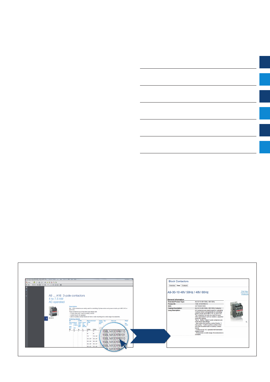
Connect to
You can access to more product details, click on the order code
IEC
(1)
AC-3 Rated operational power
θ
≤ 55 °C, 400 V
kW
4
5.5
7.5
11
15
18.5
22
30
37
45
55
75
90
110
140
160
UL/CSA 3-phase motor rating
480 V
hp
5
7.5
10
20
25
30
40
60
60
60
75
100
125
150
200
250
AC Control supply
Type
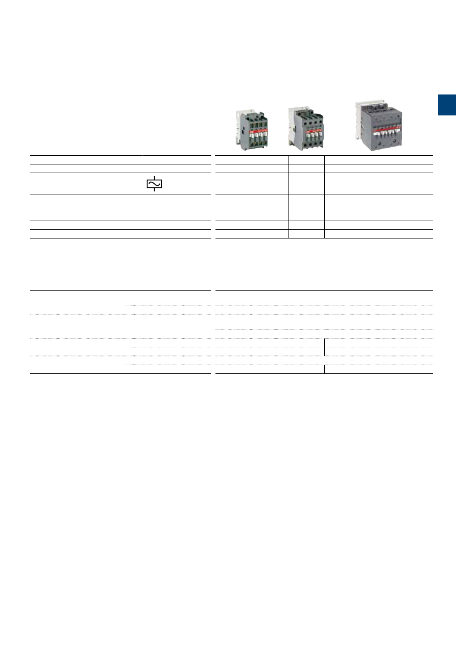
A9
A12
A16
A26
A30
A40
A50
A63
A75
A95
A110
A145
A185
A210
A260
A300
IEC
AC-3 Rated operational current
θ
≤ 55 °C , 400 V
A
9
12
17
26
32
37
50
65
75
96
110
145
185
210
260
305
AC-1 Rated operational current
θ
≤ 40 °C, 690 V
A
25
27
30
45
55
60
100
115
125
145
160
250
275
350
400
500
UL/CSA General use rating
600 V
A
21
25
30
40
50
60
80
90
105
125
150
230
250
300
350
400
NEMA
NEMA Size
00
0
—
1
1P
—
2
—
3
—
—
4
—
—
5
—
(1) 1000 V IEC ratings available for A50 ... A300 contactors.
Main accessories
Auxiliary contact blocks
Front mounting
CA5-10
(1 x N.O.)
CA5-01
(1 x N.C.)
Side mounting
CAL5-11
(1 x N.O. + 1 x N.C.)
CAL18-11
(1 x N.O. + 1 x N.C.)
Timers
Electronic
TEF5-ON
TEF5-OFF
TE5S
(for star-delta starters - direct timing - separate mounting)
Interlocking units
Mechanical
VM5-1
VM300H
VM300V
Mechanical / Electrical
VE5-1
VE5-2
Surge suppressors
Varistor (AC/DC)
RV5
(24...440 V)
RC Type (AC)
RC5-1
(24...440 V)
RC5-2
(24...440 V)
RC5-3
(250...440 V)
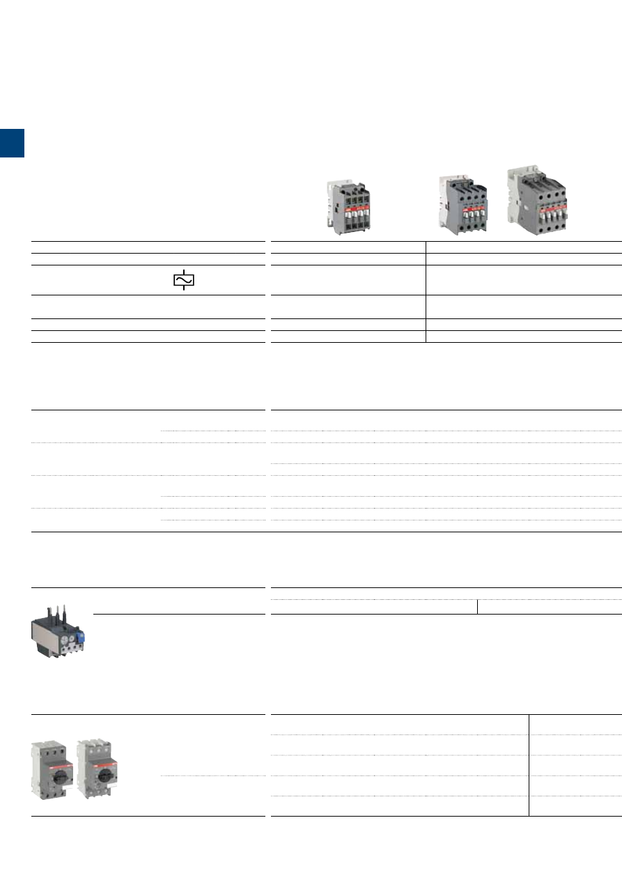
Overload relays
Thermal relays
Class 10A
(Class 10A or 20 for TA80DU)
(Class 30 for TA450SU)
TA25DU-M
(0.10…32 A)
TA75DU-M
(18…80 A)
TA80DU
(29...80 A)
TA200DU
(66...200 A)
TA450DU
(130...310 A)
TA42DU-M
(18…42 A)
TA110DU
(66...110 A)
TA450SU
(40...310 A)
Manual motor starters
Short-circuit protection devices
Thermal / magnetic protection
Class 10
MS116
(0.10...32 A)
lcs up to 50 kA for class 10 A
MS450
(28...50 A)
lcs up to 50 kA
Tmax
Circuit breaker and accessories
MS132
(0.10...32 A)
lcs up to 100 kA
MS495
(45…100 A)
Ics up to 50 kA
MS497
(22…100 A)
Ics up to 100 kA
Magnetic only types
MO132
(0.16...32 A)
Ics up to 100 kA
MO496
(32…100 A)
Ics up to 100 kA
MO450
(40…50 A)
Ics up to 50 kA
MO495
(63…100 A)
Ics up to 50 kA
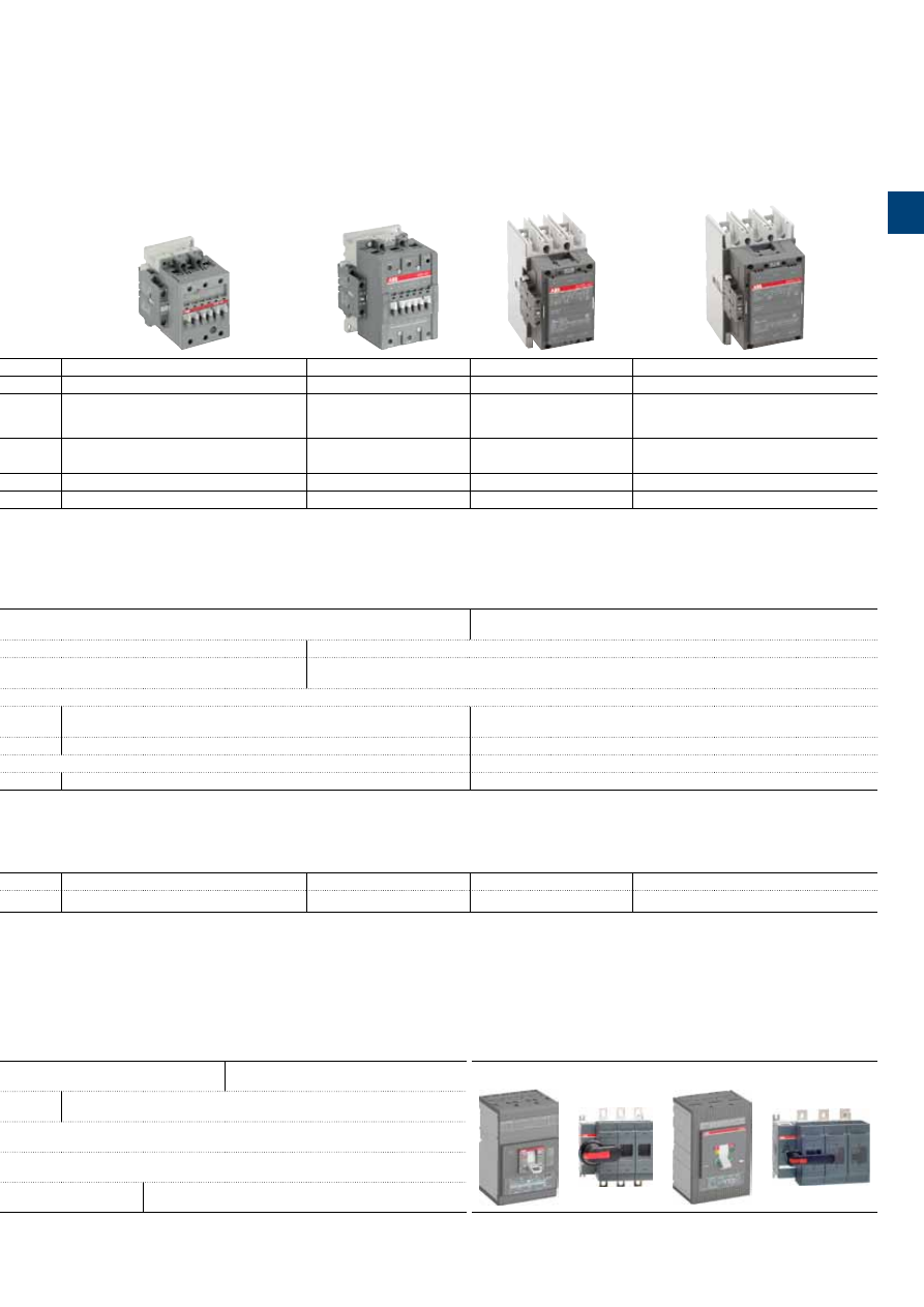
3-pole contactors, for motor control and power switching
1
/2 |
ABB
1
IEC
(1)
AC-3 Rated operational power
θ
≤ 55 °C, 400 V
kW
4
5.5
7.5
11
15
18.5
22
30
37
45
55
75
90
110
140
160
UL/CSA 3-phase motor rating
480 V
hp
5
7.5
10
20
25
30
40
60
60
60
75
100
125
150
200
250
AC Control supply
Type
A9
A12
A16
A26
A30
A40
A50
A63
A75
A95
A110
A145
A185
A210
A260
A300
IEC
AC-3 Rated operational current
θ
≤ 55 °C , 400 V
A
9
12
17
26
32
37
50
65
75
96
110
145
185
210
260
305
AC-1 Rated operational current
θ
≤ 40 °C, 690 V
A
25
27
30
45
55
60
100
115
125
145
160
250
275
350
400
500
UL/CSA General use rating
600 V
A
21
25
30
40
50
60
80
90
105
125
150
230
250
300
350
400
NEMA
NEMA Size
00
0
—
1
1P
—
2
—
3
—
—
4
—
—
5
—
(1) 1000 V IEC ratings available for A50 ... A300 contactors.
Main accessories
Auxiliary contact blocks
Front mounting
CA5-10
(1 x N.O.)
CA5-01
(1 x N.C.)
Side mounting
CAL5-11
(1 x N.O. + 1 x N.C.)
CAL18-11
(1 x N.O. + 1 x N.C.)
Timers
Electronic
TEF5-ON
TEF5-OFF
TE5S
(for star-delta starters - direct timing - separate mounting)
Interlocking units
Mechanical
VM5-1
VM300H
VM300V
Mechanical / Electrical
VE5-1
VE5-2
Surge suppressors
Varistor (AC/DC)
RV5
(24...440 V)
RC Type (AC)
RC5-1
(24...440 V)
RC5-2
(24...440 V)
RC5-3
(250...440 V)
Overload relays
Thermal relays
Class 10A
(Class 10A or 20 for TA80DU)
(Class 30 for TA450SU)
TA25DU-M
(0.10…32 A)
TA75DU-M
(18…80 A)
TA80DU
(29...80 A)
TA200DU
(66...200 A)
TA450DU
(130...310 A)
TA42DU-M
(18…42 A)
TA110DU
(66...110 A)
TA450SU
(40...310 A)
Manual motor starters
Short-circuit protection devices
Thermal / magnetic protection
Class 10
MS116
(0.10...32 A)
lcs up to 50 kA for class 10 A
MS450
(28...50 A)
lcs up to 50 kA
Tmax
Circuit breaker and accessories
MS132
(0.10...32 A)
lcs up to 100 kA
MS495
(45…100 A)
Ics up to 50 kA
MS497
(22…100 A)
Ics up to 100 kA
Magnetic only types
MO132
(0.16...32 A)
Ics up to 100 kA
MO496
(32…100 A)
Ics up to 100 kA
MO450
(40…50 A)
Ics up to 50 kA
MO495
(63…100 A)
Ics up to 50 kA
1S
B
C
101
87
5
S
0
2
01
ABB
|
1
/3
1
1
/4 |
ABB
N3
1
4-pole contactors
IEC
AC-1 Rated operational current
θ
≤ 40 °C, 690 V
A
25
30
45
70
100
125
UL/CSA General use rating
600 V
A
21
30
40
65
80
105
AC Control supply
Type
A9
A16
A26
A45
A50
A75
IEC
AC-1 Rated operational current
θ
≤ 40 °C
A
25
30
45
70
100
125
θ
≤ 55 °C
A
22
27
40
60
85
105
θ
≤ 70 °C
A
18
23
32
50
70
85
With conductor cross sectional area
mm
2
2.5
4
6
25
35
50
Rated operational voltage Ue max.
V
690
690
690
1000
1000
1000
Main accessories
Auxiliary contact blocks
Front mounting
CA5-10
(1 x N.O.)
CA5-01
(1 x N.C.)
Side mounting
CAL5-11
(1 x N.O. + 1 x N.C.)
Timers
Electronic
TEF5-ON
TEF5-OFF
TE5S
(for star-delta starters - direct timing - separate mounting)
Interlocking units
Mechanical
VM5-1
Mechanical / Electrical
VE5-1
VE5-2
Surge suppressors
Varistor (AC / DC)
RV5
(24...440 V)
RC Type (AC)
RC5-1
(24...440 V)
RC5-2
(24...440 V)
1S
B
C
101
8
8
4
S
0
2
01
ABB
|
1
/5
1
S
umma
ry
_2
2
2
/0
| ABB

Manual motor starters
S
umma
ry
_2
2
ABB
|
2
/1
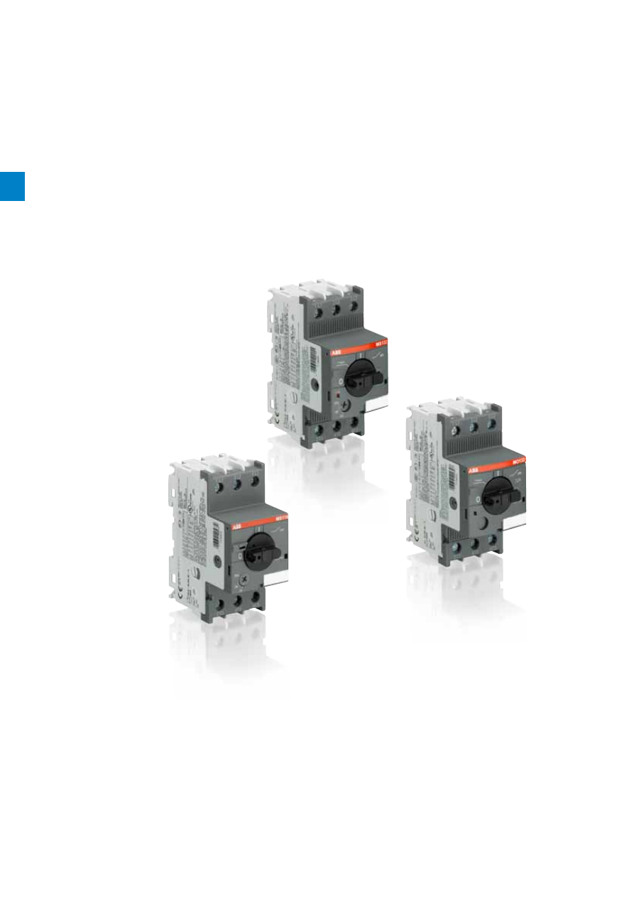
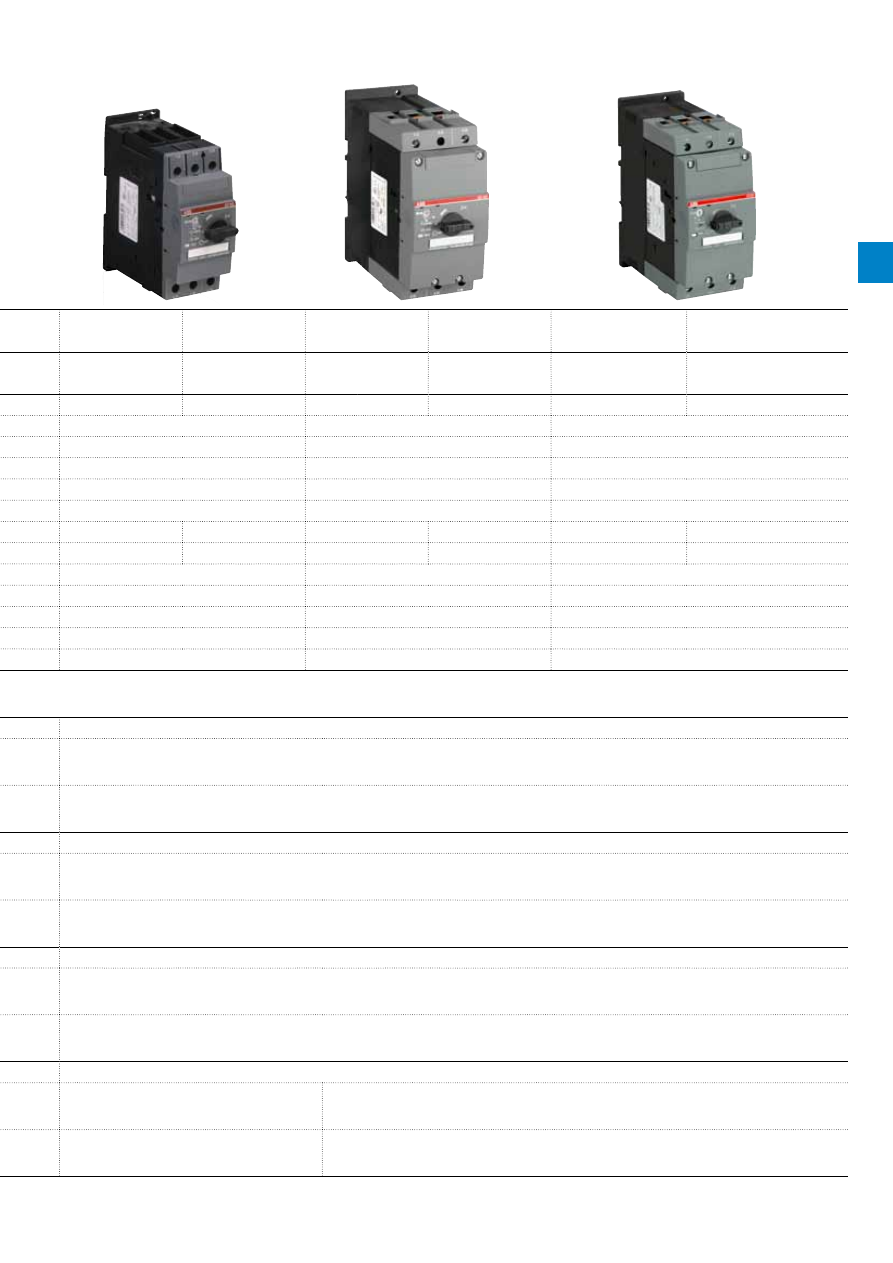
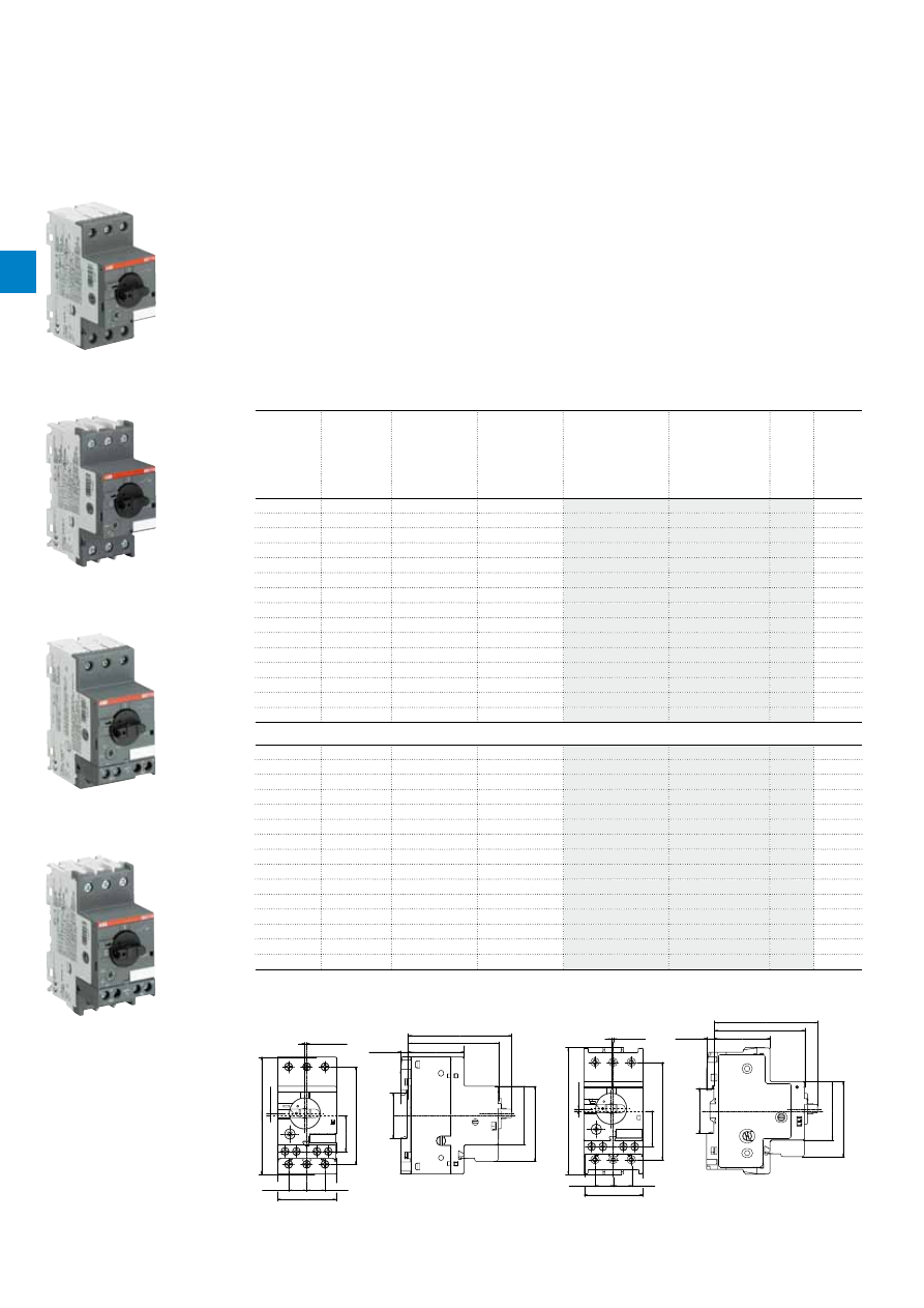
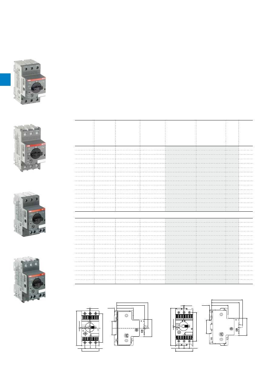
0.10 to 32 A – with thermal and electromagnetic protection
0.16 to 32 A – with electromagnetic protection
Main accessories for MS116, MS132, MO132
22 to 100 A – with thermal and electromagnetic protection
MS450, MS495, MS497 manual motor starters
32 to 100 A – with electromagnetic protection
MO450, MO495, MO496 manual motor starters
Main accessories for MS450, MS495, MS497, MO450,
MO495, MO496
2CDC241010F0011
1SBC101232F0010
2CDC241004F0009
1SBC101184F0014
2CDC241020F0011
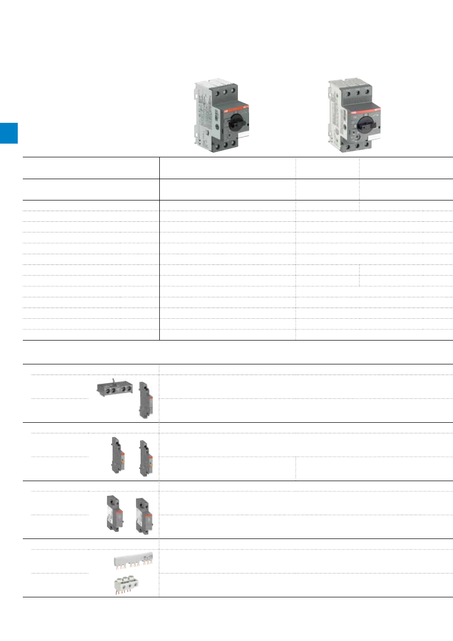
Thermal and electromagnetic
protection
Type MS116
MS132
MS450
MS495
MS497
Electromagnetic protection
Type -
MO132
MO450
MO495
MO496
Phase loss sensitivity
Yes
Yes
No
Yes
No
Yes
No
Yes
No
Switch position
ON/OFF
ON/OFF/TRIP
ON/OFF/TRIP
ON/OFF/TRIP
ON/OFF/TRIP
Magnetic trip indication
-
Yes
-
-
-
Lockable handle without accessories
-
Yes
Yes
Yes
Yes
Disconnecting feature
Yes
Yes
Yes
Yes
Yes
Width
45 mm
45 mm
55 mm
70 mm
70 mm
Rated operational current Ie
0.16...32 A
0.16....32 A
0.16....32 A
40...50 A
40...50 A
63...100 A
63...100 A
32...100 A
32...100 A
Setting range for thermal release
0.10...32 A
0.10....32 A
-
28...50 A
-
45...100 A
-
22...100 A
-
Rated operational voltage Ue
690 V AC
690 V AC / 250 V DC
690 V AC / 440 V DC
690 V AC / 440 V DC
690 V AC / 440 V DC
Rated frequency
50/60 Hz
DC, 50/60 Hz
DC, 50/60 Hz
DC, 50/60 Hz
DC, 50/60 Hz
Trip class
10A
10
10
10
10
Short-circuit breaking capacity Ics
400 V AC
Up to 50 kA
Up to 100 kA
Up to 50 kA
Up to 50 kA
Up to 100 kA
Ambient air temperature open compensated
-25...+55 °C
-25...+60 °C
-20...+60 °C
-20...+60 °C
-20...+60 °C
Main accessories
Auxiliary contacts
Front mounting
HKF1
HK4
Side mounting
HK1
HKS4
Signalling contacts
Tripped alarm
SK1
SK4
Short-circuit alarm
-
CK1
SK4
Auxiliary trip units
Shunt trip
AA1
AA4
Undervoltage release
UA1
UA4
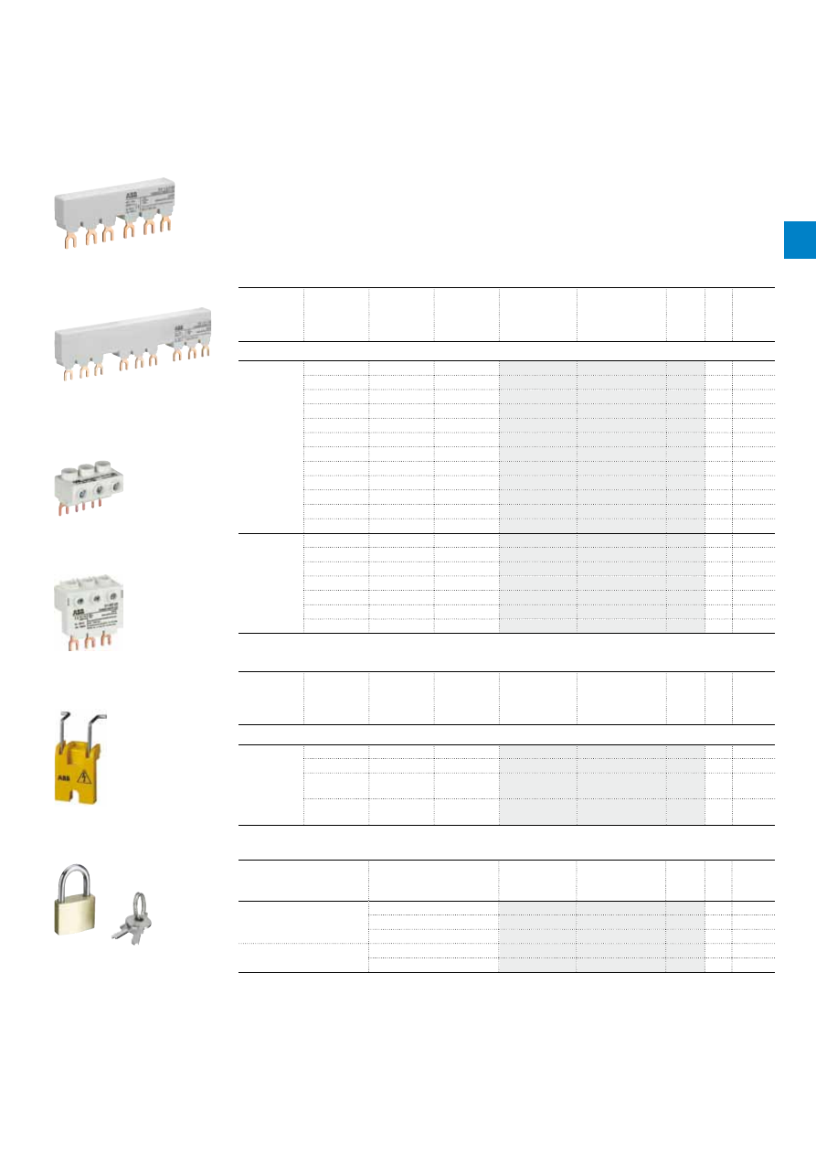
Busbar systems
3-phase busbar
PS1
PS4
-
Feeder terminals
S1
S4
-
Manual motor starters
2
/2 |
ABB
2
2CDC241010F0011
1SBC101232F0010
2CDC241004F0009
1SBC101184F0014
2CDC241020F0011
Thermal and electromagnetic
protection
Type MS116
MS132
MS450
MS495
MS497
Electromagnetic protection
Type -
MO132
MO450
MO495
MO496
Phase loss sensitivity
Yes
Yes
No
Yes
No
Yes
No
Yes
No
Switch position
ON/OFF
ON/OFF/TRIP
ON/OFF/TRIP
ON/OFF/TRIP
ON/OFF/TRIP
Magnetic trip indication
-
Yes
-
-
-
Lockable handle without accessories
-
Yes
Yes
Yes
Yes
Disconnecting feature
Yes
Yes
Yes
Yes
Yes
Width
45 mm
45 mm
55 mm
70 mm
70 mm
Rated operational current Ie
0.16...32 A
0.16....32 A
0.16....32 A
40...50 A
40...50 A
63...100 A
63...100 A
32...100 A
32...100 A
Setting range for thermal release
0.10...32 A
0.10....32 A
-
28...50 A
-
45...100 A
-
22...100 A
-
Rated operational voltage Ue
690 V AC
690 V AC / 250 V DC
690 V AC / 440 V DC
690 V AC / 440 V DC
690 V AC / 440 V DC
Rated frequency
50/60 Hz
DC, 50/60 Hz
DC, 50/60 Hz
DC, 50/60 Hz
DC, 50/60 Hz
Trip class
10A
10
10
10
10
Short-circuit breaking capacity Ics
400 V AC
Up to 50 kA
Up to 100 kA
Up to 50 kA
Up to 50 kA
Up to 100 kA
Ambient air temperature open compensated
-25...+55 °C
-25...+60 °C
-20...+60 °C
-20...+60 °C
-20...+60 °C
Main accessories
Auxiliary contacts
Front mounting
HKF1
HK4
Side mounting
HK1
HKS4
Signalling contacts
Tripped alarm
SK1
SK4
Short-circuit alarm
-
CK1
SK4
Auxiliary trip units
Shunt trip
AA1
AA4
Undervoltage release
UA1
UA4
Busbar systems
3-phase busbar
PS1
PS4
-
Feeder terminals
S1
S4
-
ABB
|
2
/3
2C
D
C
13
10
4
6
C
0
2
01
2
2C
D
C
13
10
3
9
C
0
2
01
2
/4 |
ABB
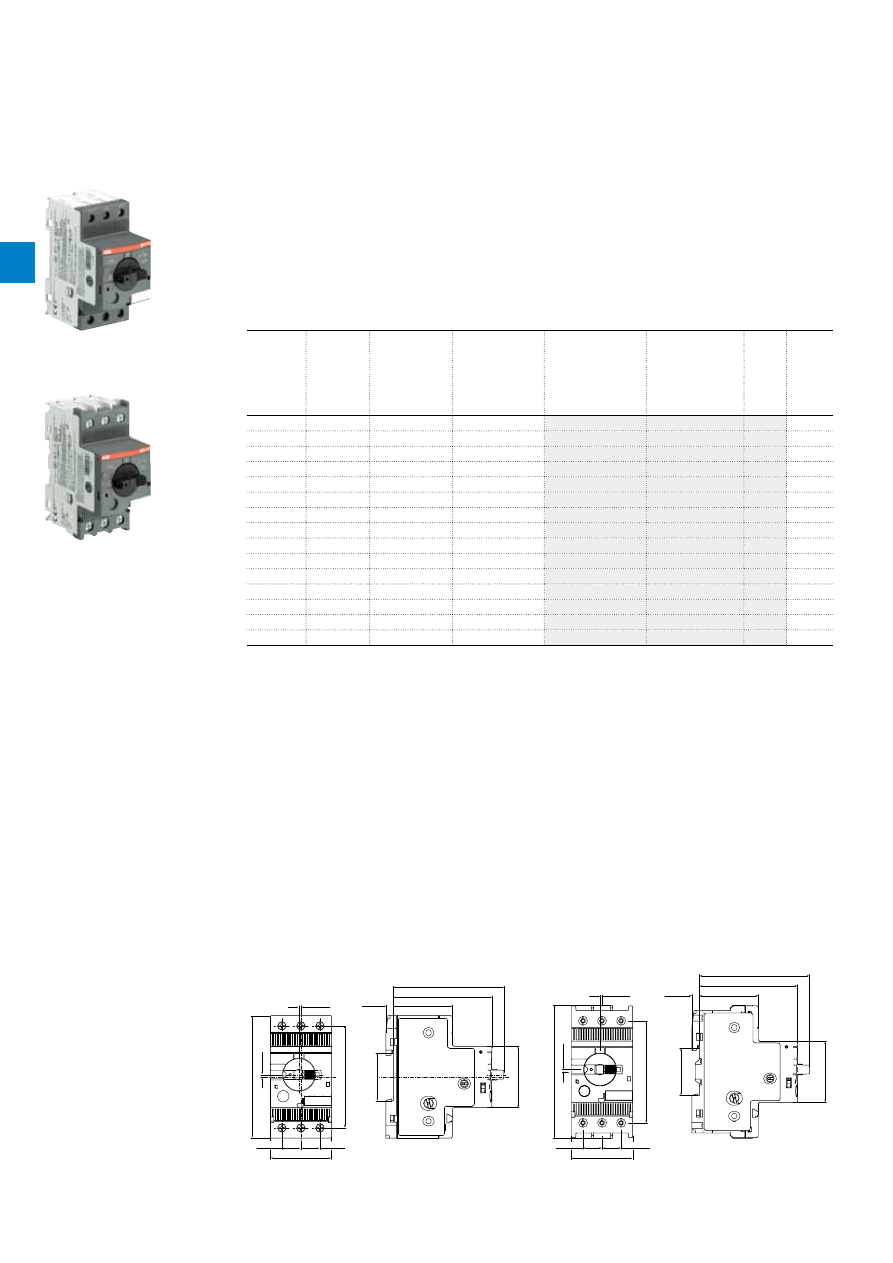
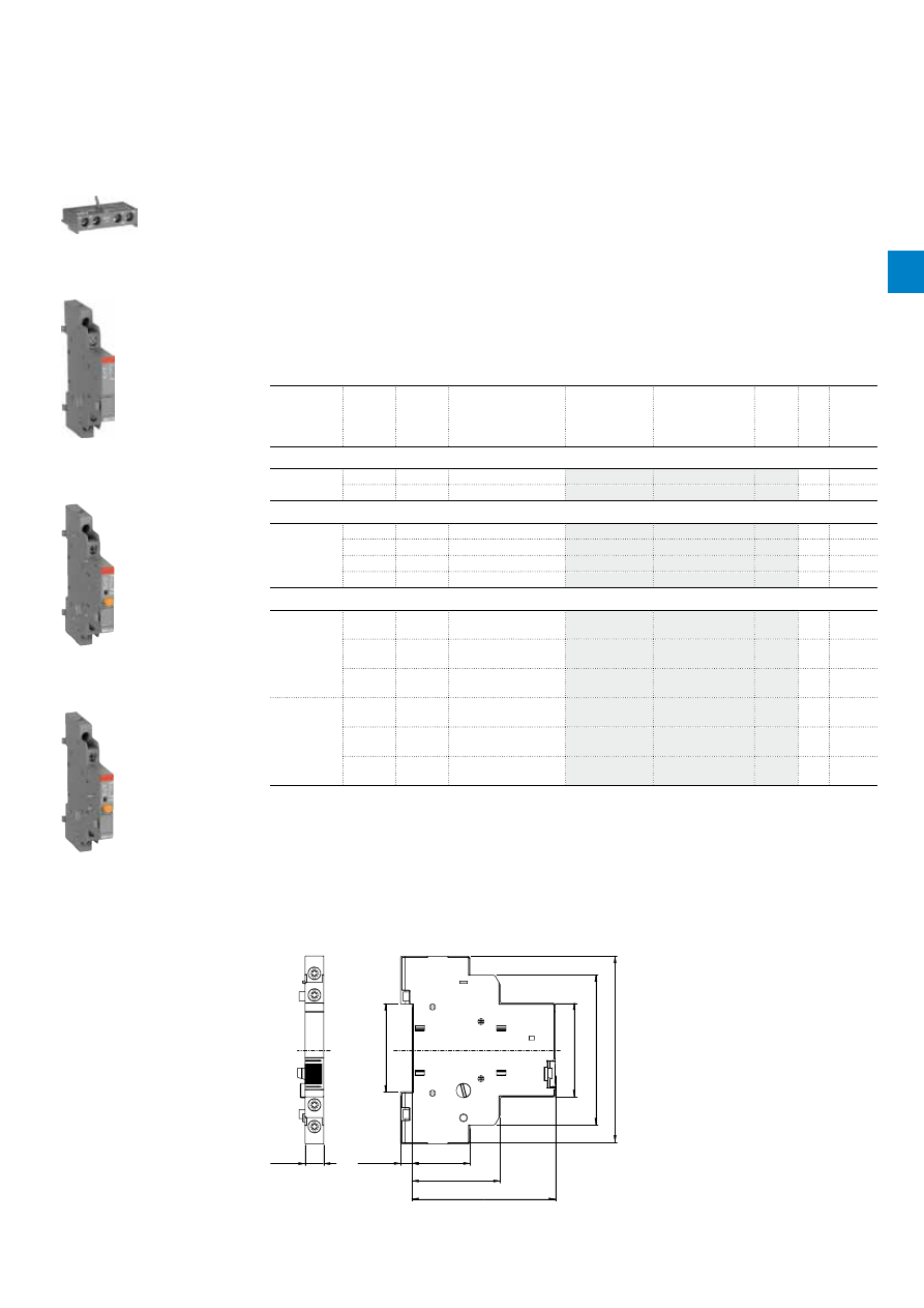
MS116 manual motor starters
0.10 to 32 A – with thermal and electromagnetic protection
Description
Manual motor starters (MMS) are protection devices for the main circuit. They combine motor control and
protection in a single device. MMS are used mainly to switch motors manually ON/OFF and protect them
and the installation fuse less against short-circuit, overload and phase failures. Fuse less protection with
a manual motor starter saves costs, space and ensures a quick reaction under short-circuit condition, by
switching off the motor within milliseconds.
MS116 is a compact and economic range for motor protection up to 15.5 kW (400 V) / 32 A in width of 45 mm.
Further features are the build-in disconnect function, temperature compensation, trip-free mechanism and
a rotary handle with a clear switch position indication. The manual motor starter is suitable for three- and
single-phase applications. Auxiliary contacts, signalling contacts, undervoltage releases, shunt trips, three-
phase bus bars, power in-feed blocks and locking devices for protection against unauthorized changes
are available as accessory.
Ordering details
Rated
operational
power
400 V
AC-3
Setting range Short-circuit
breaking
capacity Ics at
400 V AC
Rated
instantaneous
short-circuit
current setting li
Type
Order code
Weight
(1 pce)
kW
A
kA
A
kg
0.03
0.10...0.16
50
1.56
MS116-0.16
0.225
0.06
0.16...0.25
50
2.44
MS116-0.25
0.225
0.09
0.25...0.40
50
3.90
MS116-0.4
0.225
0.12
0.40...0.63
50
6.14
MS116-0.63
0.225
0.25
0.63...1.00
50
11.50
MS116-1.0
0.225
0.55
1.00...1.60
50
18.40
MS116-1.6
0.265
0.75
1.60...2.50
50
28.75
MS116-2.5
0.265
1.5
2.50...4.00
50
50.00
MS116-4.0
0.265
2.2
4.00...6.30
50
78.75
MS116-6.3
0.265
4.0
6.30...10.0
50
150
MS116-10
0.265
5.5
8.00...12.0
25
180
MS116-12
0.265
7.5
10.0...16.0
16
240
MS116-16
0.265
9.0
16.0...20.0
10
300
MS116-20
0.310
12.5
20.0...25.0
10
375
MS116-25
0.310
15.5
25.0...32.0
10
480
MS116-32
0.310
Auxiliary contacts mounted on the front (1 N.O. + 1 N.C.)
0.03
0.10...0.16
50
1.56
MS116-0.16-HKF1-11 1SAM250005R1001
0.240
0.06
0.16...0.25
50
2.44
MS116-0.25-HKF1-11 1SAM250005R1002
0.240
0.09
0.25...0.40
50
3.90
MS116-0.4-HKF1-11
0.240
0.12
0.40...0.63
50
6.14
MS116-0.63-HKF1-11 1SAM250005R1004
0.240
0.25
0.63...1.00
50
11.50
MS116-1.0-HKF1-11
0.240
0.55
1.00...1.60
50
18.40
MS116-1.6-HKF1-11
0.280
0.75
1.60...2.50
50
28.75
MS116-2.5-HKF1-11
0.280
1.5
2.50...4.00
50
50.00
MS116-4.0-HKF1-11
0.280
2.2
4.00...6.30
50
78.75
MS116-6.3-HKF1-11
0.280
4.0
6.30...10.0
50
150
MS116-10.0-HKF1-11 1SAM250005R1010
0.280
5.5
8.00...12.0
25
180
MS116-12.0-HKF1-11 1SAM250005R1012
0.280
7.5
10.0...16.0
16
240
MS116-16.0-HKF1-11 1SAM250005R1011
0.280
9.0
16.0...20.0
10
300
MS116-20-HKF1-11
0.326
12.5
20.0...25.0
10
375
MS116-25-HKF1-11
0.326
15.5
25.0...32.0
10
480
MS116-32-HKF1-11
0.326
2CDC241010F0011
MS116-16
2CDC241001F0011
MS116-25
2CDC241013F0011
MS116-0.16-HKF1-11
2CDC241012F0011
MS116-32-HKF1-11
Main dimensions
mm,
inches
0.06"
0.07"
0.55"
3.54"
1.77"
0.55"
1.38"
0.22"
1.77"
2.3"
2.76"
1.71"
3.15"
1.1"
2.95"
1.5
1.7
14
14
90
45
35
5.5
45
57.8
70
43.5
80.1
27.5
75
2CDC242002F0010
1.77"
2.3"
1.38"
0.22"
2.75"
1.7"
3.15"
0.55"
2.95"
3.85"
1.77"
0.55"
0.06"
0.07"
1.1"
45
57.8
35
5.5
69.8
43.3
79.9
14
14
75
97.8
45
1.5
1.7
27.5
2CDC242001F0011
MS116 ≤ 16 A & MS116-HKF1-11 ≤ 16 A
MS116 ≥ 20 A & MS116-HKF1-11 ≥ 20 A
2
2C
D
C
13
10
3
9
C
0
2
01
ABB
|
2
/5
MS116 manual motor starters
Technical data
Main circuit – Utilization characteristics according to IEC/EN
Type
MS116
Standards
IEC/EN 60947–2, IEC/EN 60947-4-1, IEC/EN 60947-1
Rated operational voltage U
e
690 V AC
Rated frequency
50/60 Hz
Trip class
10A
Number of poles
3
Duty time
100 %
Mechanical durability
100000 cycles
Electrical durability
up to 16 A
100000 cycles
20 ... 32 A
50000 cycles
Rated impulse withstand voltage U
imp
6 kV
Rated insulation voltage U
i
690 V AC
Rated operational current I
e
See ordering details
Rated instantaneous short-circuit current setting I
i
See ordering details
Rated service short-circuit breaking capacity I
cs
See table "Short-circuit breaking capacity and back-up fuses"
Rated ultimate short-circuit breaking capacity I
cu
See table "Short-circuit breaking capacity and back-up fuses"
Short-circuit breaking capacity and back-up fuses
l
CS
Rated service short-circuit breaking capacity
l
CU
Rated ultimate short-circuit breaking capacity
I
CC
Prospective short-circuit current at installation location
Note: Maximum rated current of the back-up fuses if I
CC
> I
CS
Type
230 V AC
400 V AC
440 V AC
500 V AC
690 V AC
I
CS
kA
I
CU
kA
gG, aM
A
I
CS
kA
I
CU
kA
gG, aM
A
I
CS
kA
I
CU
kA
gG, aM
A
I
CS
kA
I
CU
kA
gG, aM
A
I
CS
kA
I
CU
kA
gG, aM
A
MS116-0.16
No back-up fuse required up to I
CC
= 50 kA
No back-up fuse required up to I
CC
= 30 kA
MS116-0.25
MS116-0.4
MS116-0.63
MS116-1.0
MS116-1.6
MS116-2.5
10
10
25
10
10
25
5
5
25
MS116-4.0
6
6
25
6
6
25
2
2
25
MS116-6.3
6
6
63
6
6
63
2
2
40
MS116-10
6
6
63
6
6
63
2
2
50
MS116-12
25
25
80
25
25
80
6
6
63
6
6
63
2
2
50
MS116-16
16
16
80
16
16
80
6
6
63
4
4
63
2
2
63
MS116-20
10
15
-
10
15
-
3
6
-
3
4
-
2
2
-
MS116-25
10
15
-
10
15
-
3
6
-
3
4
-
2
2
-
MS116-32
10
10
-
10
10
-
3
6
-
3
4
-
2
2
-
MS116-10: No need for back-up fuse in networks with a prospective current of up to 50 kA at 400 V.
MS116-16: No need for back-up fuse in networks with a prospective current of up to 16 kA at 400 V.
With an approbiate 80 A type gG fuse the device can be used in a network with a prospective current of up to 100 kA.
MS116-32: No need for back-up fuse in networks with a prospective current of up to 10 kA at 400 V.
2
2C
D
C
13
10
3
9
C
0
2
01
2
/6 |
ABB
MS116 manual motor starters
Technical data
Main circuit – Utilization characteristics according to UL/CSA
Type
MS116
Standards
UL 508, CSA 22.2 No. 14
Maximum operational voltage
600 V AC
Manual motor controller ratings
See table "UL 508 – Manual motor controller"
Trip rating
125 % FLA
Motor ratings
Horse power
See table "Motor rating, three phase"
Full load amps (FLA)
See table "Motor rating, three phase"
Locked rotor amps (LRA)
See table "Motor rating, three phase"
Motor rating, three phase
hp
Horse power
FLA Full load amps
LRA Locked rotor amps
Type
220-240 V AC
440-480 V AC
500-600 V AC
hp
FLA
LRA
hp
FLA
LRA
hp
FLA
LRA
MS116-0.16
-
0.16
0.96
-
0.16
0.96
-
0.16
0.96
MS116-0.25
-
0.25
1.5
-
0.25
1.5
-
0.25
1.5
MS116-0.4
-
0.4
2.4
-
0.4
2.4
-
0.4
2.4
MS116-0.63
-
0.63
3.78
-
0.63
3.78
-
0.63
3.78
MS116-1.0
-
1.0
6.0
1.0
6.0
1/2
0.9
8
MS116-1.6
-
1.6
9.6
3/4
1.6
12.5
3/4
1.3
10
MS116-2.5
1/2
2.2
20
1
2.1
15
1-1/2
2.4
16
MS116-4.0
1
4.2
30
2
3.4
25
3
3.9
25.6
MS116-6.3
1-1/2
6.4
40
3
4.8
32
5
6.1
36.8
MS116-10
3
9.6
64
5
7.6
46
7-1/2
9
50.8
MS116-12
3
9.6
64
7-1/2
11
63.5
10
11
64.8
MS116-16
5
15.2
92
10
14
81
10
11
64.8
MS116-20
5
15.2
92
10
14
81
15
17
93
MS116-25
7-1/2
22
127
15
21
116
20
22
116
MS116-32
10
28
162
20
27
145
25
27
146
UL 508 – Manual motor controller
Type
Maximum fuse type K5 o. RK5
per UL/NEC
Maximum short-circuit current
for motor disconnect
1)
for group installation
480 V / 600 V
A
480 V
kA
600 V
kA
480 V
kA
600 V
kA
MS116-0.16
100
30
5
30
5
MS116-0.25
100
30
5
30
5
MS116-0.4
100
30
5
30
5
MS116-0.63
100
30
5
30
5
MS116-1.0
100
30
5
30
5
MS116-1.6
100
30
5
30
5
MS116-2.5
100
30
5
30
5
MS116-4.0
100
18
5
18
5
MS116-6.3
100
18
5
18
5
MS116-10
100
18
5
18
5
MS116-12
100
18
5
18
5
MS116-16
100
18
5
18
5
MS116-20
100
18
5
18
5
MS116-25
100
18
5
18
5
MS116-32
100
18
5
18
5
1)
Suitable as motor disconnect only when provided with padlock SA1 or SA3...
2
2C
D
C
13
10
3
9
C
0
2
01
ABB
|
2
/7
MS116 manual motor starters
Technical data
General technical data
Type
MS116
Pollution degree
3
Phase loss sensitivity
Yes
Disconnect function acc. to IEC/EN 60947-2
Yes
Ambient air temperature
Operation
Open - compensated
-25 ... +55 °C
Open
-25 ... +70 °C
Enclosed (IB132)
0 ... +40 °C
Storage
-50 ... +80 °C
Ambient air temperature compensation
Acc. to IEC/EN60947-4-1
Maximum operating altitude permissible
2000 m
Resistance to shock acc. to IEC 60068-2-27
25g / 11 ms
Resistance to vibrations acc. to IEC 60068-2-6
5g / 3 ... 150 Hz
Mounting position
Position 1-6 (optional for single mounting)
Mounting
DIN-rail (EN 60715)
Group mounting
On request
Minimum distance to other
units same type
Horizontal
0 mm
Vertical
150 mm
Minimum distance to
electrical conductive board
Horizontal, up to 400 V
0 mm
Horizontal, up to 690 V
> 1.5 mm
Vertical
75 mm
Degree of protection
Housing
IP20
Main circuit terminals
IP20
Connecting characteristics
Main circuit
Type
MS116 ≤ 16 A
MS116 ≥ 20 A
Connecting capacity
Rigid
1 or 2 x
1 ... 4 mm²
2.5 ... 6 mm²
Flexible with ferrule
1 or 2 x
0.75 ... 2.5 mm²
1 ... 6 mm²
Flexible with insulated ferrule
1 or 2 x
0.75 ... 2.5 mm²
1 ... 6 mm²
Flexible
1 or 2 x
0.75 ... 2.5 mm²
1 ... 6 mm²
Stranded acc. to UL/CSA
1 or 2 x
AWG 16-12
AWG 12-8
Flexible acc. to UL/CSA
1 or 2 x
AWG 16-12
AWG 12-8
Stripping length
9 mm
10 mm
Tightening torques
0.8 ... 1.2 Nm / 10 … 12 Ib.in
2.0 Nm / 18 Ib.in
Connection screw
M3.5 (Pozidriv 2 / 5.5 mm)
M4 (Pozidriv 2 / 6.5 mm)
2
2C
D
C
13
10
4
0
C
0
2
01
2
/8 |
ABB
MS132 manual motor starters
0.10 to 32 A – with thermal and electromagnetic protection
Description
Manual motor starters (MMS) are protection devices for the main circuit. They combine motor control and
protection in a single device. MMS are used mainly to switch motors manually ON/OFF and protect them and
the installation fuse less against short-circuit, overload and phase failures. Fuse less protection with a manual
motor starter saves costs, space and ensures a quick reaction under short-circuit condition, by switching off
the motor within milliseconds.
MS132 is a compact and powerful range for motor protection up 15.5 kW (400 V) / 32 A in width of 45 mm.
Further features are the build-in disconnect function, temperature compensation, trip-free mechanism
and a rotary handle with a clear switch position indication. The manual motor starter is suitable for three-
and single-phase applications. The handle is lockable to protect against unauthorized changes. Auxiliary
contacts, signalling contacts, undervoltage releases, shunt trips, three-phase bus bars, power in-feed
blocks.
Ordering details
Rated
operational
power
400 V
AC-3
Setting range Short-circuit
breaking
capacity Ics at
400 V AC
Rated
instantaneous
short-circuit
current setting li
Type
Order code
Weight
(1 pce)
kW
A
kA
A
kg
0.03
0.10…0.16
100
1.56
MS132-0.16
0.215
0.06
0.16…0.25
100
2.44
MS132-0.25
0.215
0.09
0.25…0.40
100
3.90
MS132-0.4
0.215
0.12
0.40…0.63
100
6.14
MS132-0.63
0.215
0.25
0.63…1.00
100
11.50
MS132-1.0
0.215
0.55
1.00…1.60
100
18.40
MS132-1.6
0.265
0.75
1.60…2.50
100
28.75
MS132-2.5
0.265
1.5
2.50…4.00
100
50.00
MS132-4.0
0.265
2.2
4.00…6.30
100
78.75
MS132-6.3
0.265
4.0
6.30…10.0
100
150
MS132-10
0.265
5.5
8.00…12.0
100
180
MS132-12
0.310
7.5
10.0…16.0
100
240
MS132-16
0.310
9.0
16.0…20.0
100
300
MS132-20
0.310
12.5
20.0…25.0
50
375
MS132-25
0.310
15.5
25.0…32.0
25
480
MS132-32
0.310
Auxiliary contacts mounted on the front (1 N.O. + 1 N.C.)
0.03
0.10...0.16
100
1.56
MS132-0.16-HKF1-11 1SAM350005R1001
0.231
0.06
0.16...0.25
100
2.44
MS132-0.25-HKF1-11 1SAM350005R1002
0.231
0.09
0.25...0.40
100
3.90
MS132-0.4-HKF1-11
0.231
0.12
0.40...0.63
100
6.14
MS132-0.63-HKF1-11 1SAM350005R1004
0.231
0.25
0.63...1.00
100
11.50
MS132-1.0-HKF1-11
0.231
0.55
1.00...1.60
100
18.40
MS132-1.6-HKF1-11
0.281
0.75
1.60...2.50
100
28.75
MS132-2.5-HKF1-11
0.281
1.5
2.50...4.00
100
50.00
MS132-4.0-HKF1-11
0.281
2.2
4.00...6.30
100
78.75
MS132-6.3-HKF1-11
0.281
4.0
6.30...10.0
100
150
MS132-10.0-HKF1-11 1SAM350005R1010
0.281
5.5
8.00...12.0
100
180
MS132-12.0-HKF1-11 1SAM350005R1012
0.326
7.5
10.0...16.0
100
240
MS132-16.0-HKF1-11 1SAM350005R1011
0.326
9.0
16.0...20.0
100
300
MS132-20-HKF1-11
0.326
12.5
20.0...25.0
50
375
MS132-25-HKF1-11
0.326
15.5
25.0...32.0
25
480
MS132-32-HKF1-11
0.326
1SBC101232F0010
MS132-10
2CDC241001F0011
MS132-32
2CDC241014F0011
MS132-0.16-HKF1-11
2CDC241015F0011
MS132-32-HKF1-11
Main dimensions
mm,
inches
1.38"
0.1"
3.54"
2.95"
0.22"
0.06"
0.55"
1.77"
0.55"
2.85"
3.2"
1.71"
1.77"
35
1.7
90
75
5.5
1.5
14
45
14
72.4
81.25
43.5
45"
2CDC242015F0009
0.06"
0.22"
0.22"
2.84"
3.19"
0.1"
3.85"
1.77"
0.55"
0.55"
1.77"
2.95"
1.38"
1.5
5.5
43.3
72.2
81.05
1.7
97.8
45
14
14
45
75
35
2CDC242016F0009
MS132 ≤ 10 A
MS132 ≥ 12 A
2
2C
D
C
13
10
4
0
C
0
2
01
ABB
|
2
/9
MS132 manual motor starters
Technical data
Main circuit – Utilization characteristics according to IEC/EN
Type
MS132
Standards
IEC/EN 60947–2, IEC/EN 60947-4-1, IEC/EN 60947-1
Rated operational voltage U
e
690 V AC / 250 V DC
Rated frequency
DC, 50/60 Hz
Trip class
Number of poles
3
Duty time
100 %
Mechanical durability
100000 cycles
Electrical durability
50000 cycles
Rated impulse withstand voltage U
imp
6 kV
Rated insulation voltage U
i
690 V AC
Rated operational current I
e
See ordering details
Rated oprational current DC-5 I
e
3 conducting paths in series up to 250 V
See "Rated operational current I
e
"
Rated instantaneous short-circuit current setting I
i
See ordering details
Rated service short-circuit breaking capacity I
cs
See table "Short-circuit breaking capacity and back-up fuses"
Rated ultimate short-circuit breaking capacity I
cu
See table "Short-circuit breaking capacity and back-up fuses"
Rated service short-circuit breaking capacity DC I
cs
3 conducting paths in series up to 250 V
10 kA
Short-circuit breaking capacity and back-up fuses
l
CS
Rated service short-circuit breaking capacity
l
CU
Rated ultimate short-circuit breaking capacity
I
CC
Prospective short-circuit current at installation location
Note: Maximum rated current of the back-up fuses if I
CC
> I
CS
Type
230 V AC
400 V AC
440 V AC
500 V AC
690 V AC
I
CS
kA
I
CU
kA
gG, aM
A
I
CS
kA
I
CU
kA
gG, aM
A
I
CS
kA
I
CU
kA
gG, aM
A
I
CS
kA
I
CU
kA
gG, aM
A
I
CS
kA
I
CU
kA
gG, aM
A
MS132-0.16
No back-up fuse required up to I
CC
= 100 kA
MS132-0.25
MS132-0.4
MS132-0.63
MS132-1.0
MS132-1.6
MS132-2.5
MS132-4.0
20
20
35
20
20
35
3
3
32
MS132-6.3
20
20
63
20
20
63
3
3
50
MS132-10
20
20
100
20
20
100
3
3
50
MS132-12
20
20
100
20
20
100
3
3
63
MS132-16
20
20
125
20
20
125
3
3
63
MS132-20
20
20
125
20
20
125
3
3
80
MS132-25
50
50
125
50
50
125
20
20
125
10
10
125
3
3
100
MS132-32
25
50
125
25
50
125
20
20
125
10
10
125
3
3
100
MS132-16: No need for back-up fuse in networks with a prospective current of up to 100 kA at 400 V.
MS132-32: No need for back-up fuse in networks with a prospective current of up to 50 kA at 400 V.
With an approbiate 125 A type gG fuse the device can be used in a network with a prospective current of up to 100 kA.
2
2C
D
C
13
10
4
0
C
0
2
01
2
/10 |
ABB
MS132 manual motor starters
Technical data
Main circuit – Utilization characteristics according to UL/CSA
Type
MS132
Standards
UL 508, CSA 22.2 No. 14
Maximum operational voltage
600 V AC
Manual motor controller ratings
See table "UL 508 – Manual motor controller"
Trip rating
125 % FLA
Motor ratings
Horse power
See table "Motor rating, three phase"
Full load amps (FLA)
See table "Motor rating, three phase"
Locked rotor amps (LRA)
See table "Motor rating, three phase"
Motor rating, single phase
hp
Horse power
FLA Full load amps
LRA Locked rotor amps
Type
120 V AC
220-240 V AC
hp
FLA
LRA
hp
FLA
LRA
MS132-0.16
-
0.16
0.96
-
0.16
0.96
MS132-0.25
-
0.25
1.5
-
0.25
1.5
MS132-0.4
-
0.4
2.4
-
0.4
2.4
MS132-0.63
-
0.63
3.78
-
0.63
3.78
MS132-1.0
-
1
6
-
1
6
MS132-1.6
1.6
9.6
1/10
1.6
9.6
MS132-2.5
2.5
15
1/6
2.5
15
MS132-4.0
1/8
4
24
1/3
4
24
MS132-6.3
1/4
6.3
37.8
1/2
6.3
37.8
MS132-10
1/2
9.8
58.8
1-1/2
10
60
MS132-12
1/2
9.8
58.8
2
12
72
MS132-16
1
16
96
2
12
72
MS132-20
1-1/2
20
120
3
17
92
MS132-25
2
24
144
3
17
127
MS132-32
2
24
144
5
28
162
Motor rating, three phase
hp
Horse power
FLA Full load amps
LRA Locked rotor amps
Type
220-240 V AC
440-480 V AC
500-600 V AC
hp
FLA
LRA
hp
FLA
LRA
hp
FLA
LRA
MS132-0.16
-
0.16
0.96
-
0.16
0.96
-
0.16
0.96
MS132-0.25
-
0.25
1.5
-
0.25
1.5
-
0.25
1.5
MS132-0.4
-
0.4
2.4
-
0.4
2.4
-
0.4
2.4
MS132-0.63
-
0.63
3.78
-
0.63
3.78
-
0.63
3.78
MS132-1.0
-
1.0
6.0
-
1.0
6.0
1/2
1.0
6.0
MS132-1.6
-
1.6
9.6
3/4
1.6
9.6
3/4
1.6
9.6
MS132-2.5
1/2
2.5
15.0
1
2.5
15.0
1-1/2
2.5
15.0
MS132-4.0
1
4.0
24.0
2
4.0
24.0
3
3.9
26.0
MS132-6.3
1-1/2
6.3
37.8
3
4.8
32.0
5
6.1
37.0
MS132-10
3
9.6
64.0
5
7.6
46.0
7-1/2
9.0
51.0
MS132-12
3
9.6
64.0
7-1/2
11.0
64.0
10
11.0
65.0
MS132-16
5
15.2
92.0
10
14.0
81.0
10
11.0
65.0
MS132-20
5
15.2
92.0
10
14.0
81.0
15
17.0
93.0
MS132-25
7-1/2
22.0
127.0
15
21.0
116.0
20
22.0
116.0
MS132-32
10
28.0
162.0
20
27.0
145.0
25
27.0
146.0
2
2C
D
C
13
10
4
0
C
0
2
01
ABB
|
2
/11
MS132 manual motor starters
Technical data
UL 508 – Manual motor controller
Type
Maximum short-circuit current
for motor disconnect
for group installation
for self-protected combination motor
controller (type E) in combination with
feeder block S1-M3-xx
for tap conductor protection
480 V
kA
600 V
kA
480 V
kA
600 V
kA
480Y / 277 V
kA
600Y / 347 V
kA
480 V
kA
600 V
kA
MS132-0.16
65
47
65
47
65
47
65
47
MS132-0.25
65
47
65
47
65
47
65
47
MS132-0.4
65
47
65
47
65
47
65
47
MS132-0.63
65
47
65
47
65
47
65
47
MS132-1.0
65
47
65
47
65
47
65
47
MS132-1.6
65
47
65
47
65
47
65
47
MS132-2.5
65
47
65
47
65
47
65
47
MS132-4.0
65
18
65
30
65
18
65
18
MS132-6.3
65
18
65
30
65
18
65
18
MS132-10
65
18
65
30
65
18
65
18
MS132-12
30
18
30
30
30
-
30
18
MS132-16
30
18
30
30
30
-
30
18
MS132-20
30
18
30
30
30
-
30
18
MS132-25
30
18
30
30
30
-
30
18
MS132-32
30
18
30
30
30
-
30
18
General technical data
Type
MS132
Pollution degree
3
Phase loss sensitivity
Yes
Disconnect function acc. to IEC/EN 60947-2
Yes
Ambient air temperature
Operation
Open - compensated
-25 ... +60 °C
Open
-25 ... +70 °C
Enclosed (IB132)
0 ... +40 °C
Storage
-50 ... +70 °C
Ambient air temperature compensation
Acc. to IEC/EN60947-4-1
Maximum operating altitude permissible
2000 m
Resistance to shock acc. to IEC 60068-2-27
25g / 11 ms
Resistance to vibrations acc. to IEC 60068-2-6
5g / 3 ... 150 Hz
Mounting position
Position 1-6 (optional for single mounting)
Mounting
DIN-rail (EN 60715)
Group mounting
On request
Minimum distance to other
units same type
Horizontal
0 mm
Vertical
150 mm
Minimum distance to
electrical conductive board
Horizontal, up to 400 V
0 mm
Horizontal, up to 690 V
> 1.5 mm
Vertical
75 mm
Degree of protection
Housing
IP20
Main circuit terminals
IP20
Connecting characteristics
Main circuit
Type
MS132-0.16 … MS132-10
MS132-12 … MS132-16
MS132-20 … MS132-32
Connecting capacity
Rigid
1 or 2 x
1 ... 4 mm²
1 ... 4 mm²
2.5 ... 6 mm²
Flexible with ferrule
1 or 2 x
1 ... 4 mm²
1 ... 4 mm²
2.5 ... 6 mm²
Flexible with insulated ferrule
1 or 2 x
1 ... 4 mm²
1 ... 4 mm²
2.5 ... 6 mm²
Flexible
1 or 2 x
1 ... 4 mm²
1 ... 4 mm²
2.5 ... 6 mm²
Stranded acc. to UL/CSA
1 or 2 x
AWG 16-12
AWG 16-12
AWG 12-8
Flexible acc. to UL/CSA
1 or 2 x
AWG 16-12
AWG 16-12
AWG 12-8
Stripping length
9 mm
10 mm
10 mm
Tightening torques
0.8 ... 1.2 Nm / 10 … 12 Ib.in 1.5 Nm / 14 Ib.in
2.0 Nm / 18 Ib.in
Connection screw
M3.5 (Pozidriv 2)
M4 (Pozidriv 2)
M4 (Pozidriv 2)
2
2C
D
C
13
10
36C
0
2
01
2
/12 |
ABB
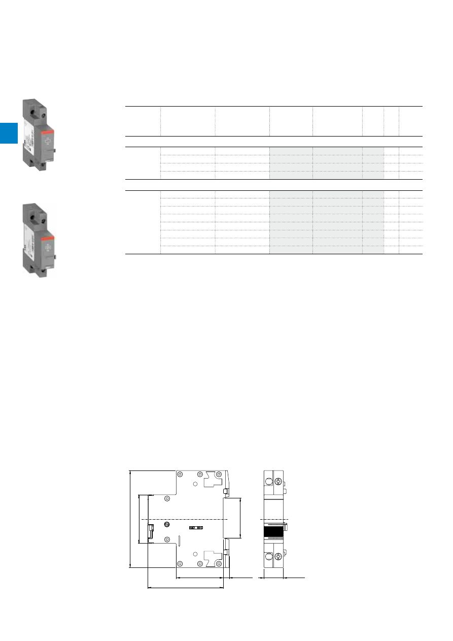
MO132 manual motor starters magnetic only
0.16 to 32 A – with electromagnetic protection
Description
Manual motor starters magnetic only are electromechanical protection devices for the main circuit. They are
used mainly to switch motors manually ON/OFF and protect them fuse less against short-circuit.
Fuse less protection with a manual motor starter saves costs, space and ensures a quick reaction under
short-circuit condition, by switching off the motor within milliseconds. Fuse less starter combinations are setup
together with contactors and overload relays.
Ordering details
Rated
operational
power
400 V
AC-3
(1)
Rated
operational
current
Short-circuit
breaking
capacity Ics at
400 V AC
Rated
instantaneous
short-circuit
current setting li
Type
Order code
Weight
(1 pce)
kW
A
kA
A
kg
0.03
0.16
100
1.56
MO132-0.16
0.215
0.06
0.25
100
2.44
MO132-0.25
0.215
0.09
0.40
100
3.90
MO132-0.4
0.215
0.12
0.63
100
6.14
MO132-0.63
0.215
0.25
1.0
100
11.50
MO132-1.0
0.215
0.55
1.6
100
18.40
MO132-1.6
0.265
0.75
2.5
100
28.75
MO132-2.5
0.265
1.5
4.0
50
50.00
MO132-4.0
0.265
2.2
6.3
50
78.75
MO132-6.3
0.265
4.0
10
50
125.00
MO132-10
0.265
5.5
12
50
150.00
MO132-12
0.310
7.5
16
50
200.00
MO132-16
0.310
9.0
20
50
250.00
MO132-20
0.310
12.5
25
50
312.50
MO132-25
0.310
15.5
32
25
400.00
MO132-32
0.310
(1) For overload protection of motors, an appropriate thermal or electronic overload relay must be used.
2CDC241009F0011
MO132-6.3
2CDC241008F0011
MO132-32
Main dimensions
mm,
inches
1.38"
0.1"
3.54"
2.95"
0.22"
0.06"
0.55"
1.77"
0.55"
2.85"
3.2"
1.71"
1.77"
35
1.7
90
75
5.5
1.5
14
45
14
72.4
81.25
43.5
45"
2CDC242005F0011
0.06"
0.22"
0.22"
2.84"
3.19"
0.1"
3.85"
1.77"
0.55"
0.55"
1.77"
2.95"
1.38"
1.5
5.5
43.3
72.2
81.05
1.7
97.8
45
14
14
45
75
35
2CDC242006F0011
MO132 ≤ 10 A
MO132 ≥ 12 A
2

2C
D
C
13
10
36C
0
2
01
ABB
|
2
/13
MO132 manual motor starters magnetic only
Technical data
Main circuit – Utilization characteristics according to IEC/EN
Type
MO132
Standards
IEC/EN 60947–2, IEC/EN 60947-4-1, IEC/EN 60947-1
Rated operational voltage U
e
690 V AC
Rated frequency
50/60 Hz
Number of poles
3
Duty time
100 %
Mechanical durability
100000 cycles
Electrical durability
50000 cycles
Rated impulse withstand voltage U
imp
6 kV
Rated insulation voltage U
i
690 V AC
Rated operational current I
e
See ordering details
Rated instantaneous short-circuit current setting I
i
See ordering details
Rated service short-circuit breaking capacity I
cs
See table "Short-circuit breaking capacity and back-up fuses"
Rated ultimate short-circuit breaking capacity I
cu
See table "Short-circuit breaking capacity and back-up fuses"
Short-circuit breaking capacity and back-up fuses
l
CS
Rated service short-circuit breaking capacity
l
CU
Rated ultimate short-circuit breaking capacity
I
CC
Prospective short-circuit current at installation location
Note: Maximum rated current of the back-up fuses if I
CC
> I
CS
Type
230 V AC
400 V AC
440 V AC
500 V AC
690 V AC
I
CS
kA
I
CU
kA
gG, aM
A
I
CS
kA
I
CU
kA
gG, aM
A
I
CS
kA
I
CU
kA
gG, aM
A
I
CS
kA
I
CU
kA
gG, aM
A
I
CS
kA
I
CU
kA
gG, aM
A
MO132-0.16
No back-up fuse required up to I
CC
= 100 kA
MO132-0.25
MO132-0.4
MO132-0.63
MO132-1.0
MO132-1.6
MO132-2.5
MO132-4.0
20
20
35
20
20
35
3
3
32
MO132-6.3
20
20
63
20
20
63
3
3
50
MO132-10
20
20
100
20
20
100
3
3
50
MO132-12
20
20
100
20
20
100
3
3
63
MO132-16
20
20
125
20
20
125
3
3
63
MO132-20
20
20
125
20
20
125
3
3
80
MO132-25
50
50
125
50
50
125
10
10
125
10
10
125
3
3
100
MO132-32
25
50
125
25
50
125
10
10
125
10
10
125
3
3
100
MO132-20: No need for back-up fuse in networks with a prospective current of up to 100 kA at 400 V.
MO132-32: No need for back-up fuse in networks with a prospective current of up to 50 kA at 400 V.
With an approbiate 125 A type gG fuse the device can be used in a network with a prospective current of up to 100 kA.
2

2C
D
C
13
10
36C
0
2
01
2
/14 |
ABB
MO132 manual motor starters magnetic only
Technical data
Main circuit – Utilization characteristics according to UL/CSA
Type
MO132
Standards
UL 508, CSA 22.2 No. 14
Maximum operational voltage
600 V AC
Manual motor controller ratings
See table "UL 508 – Manual motor controller"
Trip rating
125 % FLA
Motor ratings
Horse power
See table "Motor rating, three phase"
Full load amps (FLA)
See table "Motor rating, three phase"
Locked rotor amps (LRA)
See table "Motor rating, three phase"
Motor rating, single phase
hp
Horse power
FLA Full load amps
LRA Locked rotor amps
Type
120 V AC
220 ... 240 V AC
hp
FLA
LRA
hp
FLA
LRA
MO132-0.16
-
0.16
0.96
-
0.16
0.96
MO132-0.25
-
0.25
1.5
-
0.25
1.5
MO132-0.4
-
0.4
2.4
-
0.4
2.4
MO132-0.63
-
0.63
3.78
-
0.63
3.78
MO132-1.0
-
1
6
-
1
6
MO132-1.6
1.6
9.6
1/10
1.6
9.6
MO132-2.5
2.5
15
1/6
2.5
15
MO132-4.0
1/8
4
24
1/3
4
24
MO132-6.3
1/4
6.3
37.8
1/2
6.3
37.8
MO132-10
1/2
9.8
58.8
1-1/2
10
60
MO132-12
1/2
9.8
58.8
2
12
72
MO132-16
1
16
96
2
12
72
MO132-20
1-1/2
20
120
3
17
92
MO132-25
2
24
144
3
17
127
MO132-32
2
24
144
5
28
162
Motor rating, three phase
hp
Horse power
FLA Full load amps
LRA Locked rotor amps
Type
220 ... 240 V AC
440 ... 480 V AC
500 ... 600 V AC
hp
FLA
LRA
hp
FLA
LRA
hp
FLA
LRA
MO132-0.16
-
0.16
0.96
-
0.16
0.96
-
0.16
0.96
MO132-0.25
-
0.25
1.5
-
0.25
1.5
-
0.25
1.5
MO132-0.4
-
0.4
2.4
-
0.4
2.4
-
0.4
2.4
MO132-0.63
-
0.63
3.78
-
0.63
3.78
-
0.63
3.78
MO132-1.0
-
1
6
-
1
6
1/2
1
6
MO132-1.6
-
1.6
9.6
3/4
1.6
9.6
3/4
1.6
9.6
MO132-2.5
1/2
2.5
15
1
2.5
15
1-1/2
2.5
15
MO132-4.0
1
4
24
2
4
24
3
3.9
26
MO132-6.3
1-1/2
6.3
37.8
3
4.8
32
5
6.1
37
MO132-10
3
9.6
64
5
7.6
46
7-1/2
9
51
MO132-12
3
9.6
64
7-1/2
11
64
10
11
65
MO132-16
5
15.2
92
10
14
81
10
11
65
MO132-20
5
15.2
92
10
14
81
15
17
93
MO132-25
7-1/2
22
127
15
21
116
20
22
116
MO132-32
10
28
162
20
27
145
25
27
146
2
2C
D
C
13
10
36C
0
2
01
ABB
|
2
/15
UL 508 – Manual motor controller
Type
Circuit breaker or class R fuse per UL/NEC
480 V / 600 V
Maximum short-circuit current rating
480 V
600 V
kA
kA
MO132-0.16
with minimum interrupting rating of
35,000 rms symmetrical amperes
30
18
MO132-0.25
30
18
MO132-0.4
30
18
MO132-0.63
30
18
MO132-1.0
30
18
MO132-1.6
30
18
MO132-2.5
30
18
MO132-4.0
30
18
MO132-6.3
30
18
MO132-10
30
18
MO132-12
30
18
MO132-16
30
18
MO132-20
30
18
MO132-25
30
18
MO132-32
30
18
General technical data
Type
MO132
Pollution degree
3
Phase loss sensitivity
No
Disconnect function acc. to IEC/EN 60947-2
Yes
Ambient air temperature
Operation
Open
-25 ... +60 °C
Enclosed (IB132)
0 ... +40 °C
Storage
-50 ... +80 °C
Ambient air temperature compensation
-
Maximum operating altitude permissible
2000 m
Resistance to shock acc. to IEC 60068-2-27
25g / 11 ms
Resistance to vibrations acc. to IEC 60068-2-6
5g / 3 ... 150 Hz
Mounting position
Position 1-6 (optional for single mounting)
Mounting
DIN-rail (EN 60715)
Group mounting
On request
Minimum distance to other
units same type
Horizontal
0 mm
Vertical
150 mm
Minimum distance to
electrical conductive board
Horizontal, up to 400 V
0 mm
Horizontal, up to 690 V
> 1.5 mm
Vertical
75 mm
Degree of protection
Housing
IP20
Main circuit terminals
IP20
Connecting characteristics
Main circuit
Type
MO132-0.16 … MO132-10
MO132-12 … MO132-16
MO132-20 … MO132-32
Connecting capacity
Rigid
1 or 2 x
1 ... 4 mm²
1 ... 4 mm²
2.5 ... 6 mm²
Flexible with ferrule
1 or 2 x
0.75 ... 2.5 mm²
0.75 ... 2.5 mm²
1 ... 6 mm²
Flexible with insulated ferrule
1 or 2 x
0.75 ... 2.5 mm²
0.75 ... 2.5 mm²
1 ... 6 mm²
Flexible
1 or 2 x
0.75 ... 2.5 mm²
0.75 ... 2.5 mm²
1 ... 6 mm²
Stranded acc. to UL/CSA
1 or 2 x
AWG 16-12
AWG 16-12
AWG 12-8
Flexible acc. to UL/CSA
1 or 2 x
AWG 16-12
AWG 16-12
AWG 12-8
Stripping length
9 mm
10 mm
10 mm
Tightening torques
0.8 ... 1.2 Nm / 10 … 12 Ib.in 1.5 Nm / 14 Ib.in
2.0 Nm / 18 Ib.in
Connection screw
M3.5 (Pozidriv 2)
M4 (Pozidriv 2)
M4 (Pozidriv 2)
MO132 manual motor starters magnetic only
Technical data
2
2C
D
C
13
105
0
C0
2
01
2
/16 |
ABB
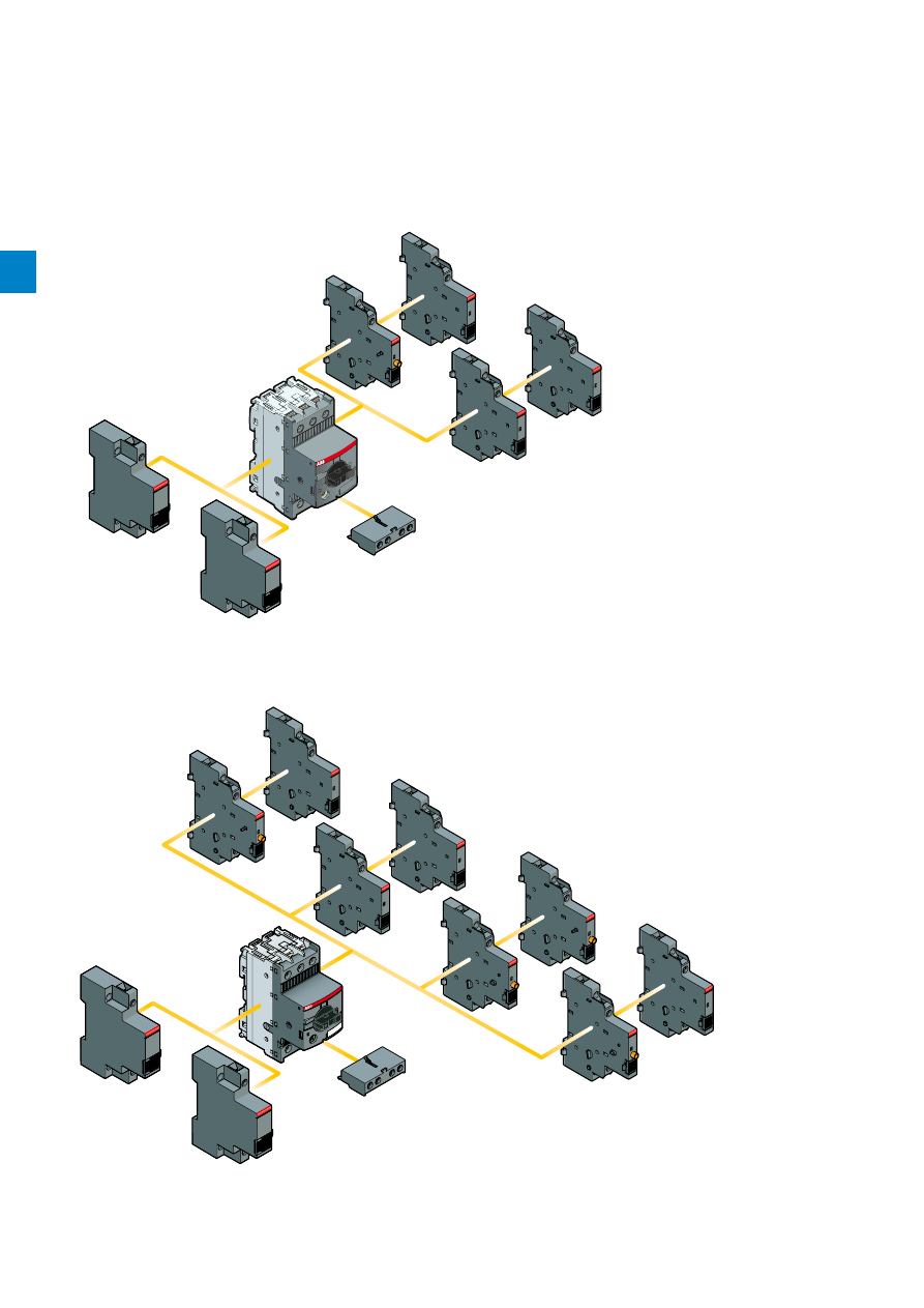
MS116, MS132, MO132 manual motor starters
Main accessories
MS116, MO132 manual motor starters with accessories
AA1
UA1
HKF1
SK1
HK1
HK1
HK1
MS116
MO132
2CDC246001F0013
MS132 manual motor starters with accessories
MS132
AA1
UA1
HKF1
SK1
HK1
HK1
HK1
CK1
CK1
HKF1
SK1
1SBC500311F0000
SK1
HK1
HK1
HK1
HKF1
UA1
AA1
MS116
MO132
SK1
SK1
HK1
HK1
HK1
HK1
CK1
CK1
HKF1
UA1
AA1
MS132
2
2C
D
C
13
105
0
C0
2
01
ABB
|
2
/17
MS116, MS132, MO132 manual motor starters
Main accessories
Description
Manual motor starters can be equipped with auxiliary contacts for lateral/front mounting, signalling contact
for lateral mounting, undervoltage release and shunt trips. Two different signalling contacts are available.
The accessories can be fitted wiring free and without tools. A variety of combinations is possible as
required for the application. The auxiliary contacts change position with the main contacts. The signalling
contact SK signals tripping regardless if it was caused by short-circuit or overload. The signalling contact
CK signals tripping in case it was caused by short-circuit. Undervoltage release are used for remote
tripping of the manual motor starter especially for emergency stop circuits. Shunt trips release the MMS
used for remote tripping.
Ordering details
Suitable for
Auxiliary
contacts
N.O.
Auxiliary
contacts
N.C.
Description
Type
Order code
Pkg
qty
Weight
(1 pce)
kg
Auxiliary contacts – mountable on the front
MS116, MS132,
MO132
1
1
HKF1-11
10
0.015
2
0
HKF1-20
10
0.015
Auxiliary contacts – mountable on the right
MS116, MS132,
MO132
1
1
max. 2 pieces
HK1-11
2
0.035
2
0
max. 2 pieces
HK1-20
2
0.035
0
2
max. 2 pieces
HK1-02
2
0.035
2
0
with lead contacts
HK1-20L
2
0.035
Signalling contacts – mountable on the right
MS116, MS132,
MO132
1
1
for tripped alarm,
max. 2 pieces
SK1-11
2
0.035
2
0
for tripped alarm,
max. 2 pieces
SK1-20
2
0.035
0
2
for tripped alarm,
max. 2 pieces
SK1-02
2
0.035
MS132
1
1
for short-circuit alarm,
max. 2 pieces
CK1-11
2
0.035
2
0
for short-circuit alarm,
max. 2 pieces
CK1-20
2
0.035
0
2
for short-circuit alarm,
max. 2 pieces
CK1-02
2
0.035
1SBC101208F0014
HKF1-11
1SBC101209F0014
HK1-11
1SBC101210F0014
SK1-11
1SBC101286F0014
CK1-11
Main dimensions
mm,
inches
5.5
42.3
27.8
68.8
9
90
72
45
42.1
3.54"
0.22"
2.83"
1.77"
1.67"
1.09"
2.71"
1.66"
0.35"
2CDC242001F0012
HK1
2
2C
D
C
13
105
0
C0
2
01
2
/18 |
ABB
MS116, MS132, MO132 manual motor starters
Main accessories
Ordering details
Suitable for
Rated control supply
voltage
Frequency
Type
Order code
Pkg
qty
Weight
(1 pce)
V
Hz
kg
Shunt trips – mountable on the left
MS116, MS132,
MO132
20...24
50/60
AA1-24
1
0.100
110
50/60
AA1-110
1
0.100
200...240
50/60
AA1-230
1
0.100
350...415
50/60
AA1-400
1
0.100
Undervoltage releases – mountable on the left
MS116, MS132,
MO132
24
50
UA1-24
1
0.100
48
50
UA1-48
1
0.100
60
50
UA1-60
1
0.100
110...120
50/60
UA1-110
1
0.100
208
60
UA1-208
1
0.100
230...240
50/60
UA1-230
1
0.100
400
50
UA1-400
1
0.100
415...480
50/60
UA1-415
1
0.100
1SBC101211F0014
AA1-24
1SBC101212F0014
UA1-24
Main dimensions
mm,
inches
90
45
5.5
43.5
70
37
18
3.54"
1.77"
1.71"
2.76"
0.22"
1.46"
0.71"
2CDC242002F0012
AA1, UA1
2
2C
D
C
13
105
0
C0
2
01
ABB
|
2
/19
General technical data
Type
HK1
SK1
HKF1
Standards
IEC/EN 60947-2, IEC/EN 60947-4-1, IEC/EN 60947-1
Rated operational voltage U
e
690 V AC / 600 DC
250 V AC / 250 V DC
Conventional free-air thermal current I
th
6 A
5 A
Rated frequency
50/60 Hz
Rated impulse withstand voltage U
imp
6 kV
Rated insulation voltage U
i
690 V AC
250 V AC
Pollution degree
3
Ambient air temperature
Operation
-25 ... +70 °C
Storage
-50 ... +80 °C
Resistance to shock acc. to IEC 60068-2-27
25g / 11 ms
Resistance to vibrations acc. to IEC 60068-2-6
5g / 3 ... 150 Hz
I
e
/ Rated operational current AC-15
acc. to IEC/EN 60947-5-1 for utilization category
24 V, 120 V
6 A
3 A
240 V
4 A
1.5 A
400 V
3 A
-
440 V, 690 V
1 A
-
I
e
/ Rated operational current DC-13
acc. to IEC/EN 60947-5-1 for utilization category
24 V
2 A
1 A
125 V
0.55 A
0.27 A
250 V
0.27 A
0.11 A
440 V, 600 V
0.15 A
-
Minimum switching capacity
17 V / 5 mA
Short-circuit protective device
N.C., 95-96
10 A Type gG
N.O., 97-98
10 A Type gG
Duty time
100 %
Mounting
Right side of MMS
Front of MMS
Mounting positions
1-6
Mechanical durability
50000 cycles
-
Electrical durability
50000 cycles
-
Connecting charateristics
Auxiliary circuit
Type
HK1
SK1
HKF1
Connecting capacity
Rigid
1 or 2 x
1 ... 1.5 mm²
1 ... 2.5 mm²
Flexible with ferrule
1 or 2 x
0.75 ... 1.5 mm²
Flexible with insulated ferrule
1 or 2 x
0.75 ... 1.5 mm²
Flexible
1 or 2 x
0.75 ... 1.5 mm²
Stranded acc. to UL/CSA
1 or 2 x
AWG 16-14
Flexible acc. to UL/CSA
1 or 2 x
AWG 16-14
Stripping length
8 mm
Tightening torques
0.8 ... 1.2 Nm / 7 Ib.in
Connection screw
M3 (Pozidriv 2)
MS116, MS132, MO132 manual motor starters
Main accessories
2
2C
D
C
13
105
0
C0
2
01
2
/20 |
ABB
MS116, MS132, MO132 manual motor starters
Main accessories
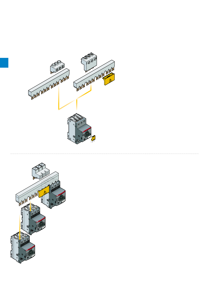
Manual motor starter with three-phase busbar systems
S1-M1-25
PS1-..-65
PS1-..-65
S1-M2-25
BS1-3
SA1
2CDC242020F0013
Three-phase busbar up to 65 A
PS1-..-100
S1-M3-35
2CDC242021F0013
Three-phase busbar up to 100 A
S1-M1-25
S1-M3-35
S1-M2-25
PS1-..-65
PS1-..-100
PS1-..-65
SA1
BS1-3
2
2C
D
C
13
105
0
C0
2
01
ABB
|
2
/21
Description
Three-phase busbars ensure a quick and safe connection and are therefore a cost effective solution.
A variety of different three-phase busbars up to 100 A are in the assortment. Between 2 and 5 manual
motor starters with none, one or two lateral auxiliary contacts can be connected. Different three-phase
feeder terminals are available according to the application.
Ordering details
Suitable for
Rated
operational
current
Number of
MMS
Number of
lateral aux.
Type
Order code
Pkg
qty
Weight
(1 pce)
A
kg
Three-phase busbars
MS116, MS132,
MO132
65
2
0
PS1-2-0-65
10
0.034
65
3
0
PS1-3-0-65
10
0.055
65
4
0
PS1-4-0-65
10
0.077
65
5
0
PS1-5-0-65
10
0.098
65
2
1
PS1-2-1-65
10
0.036
65
3
1
PS1-3-1-65
10
0.060
65
4
1
PS1-4-1-65
10
0.087
65
5
1
PS1-5-1-65
10
0.108
65
2
2
PS1-2-2-65
10
0.040
65
3
2
PS1-3-2-65
10
0.067
65
4
2
PS1-4-2-65
10
0.095
65
5
2
PS1-5-2-65
10
0.122
MS116, MS132,
MO132
100
3
0
PS1-3-0-100
10
0.084
100
4
0
PS1-4-0-100
10
0.117
100
5
0
PS1-5-0-100
10
0.154
100
3
1
PS1-3-1-100
10
0.094
100
4
1
PS1-4-1-100
10
0.134
100
5
1
PS1-5-1-100
10
0.172
100
3
2
PS1-3-2-100
10
0.105
Suitable for
Rated
operational
current
Rated cross
section
Mounting form Type
Order code
Pkg
qty
Weight
(1 pce)
A
mm²
kg
Three-phase feeder terminals
MS116, MS132,
MO132
65
25
Flat
S1-M1-25
10
0.038
65
25
High
S1-M2-25
10
0.051
65
25
UL type E and
IEC
S1-M3-25
10
0.042
100
35
UL type E and
IEC
S1-M3-35
10
0.060
Suitable for
Description
Type
Order code
Pkg
qty
Weight
(1 pce)
kg
MS116, MS132, MO132
Protection cover for busbars
BS1-3
50
0.003
Screw fixing kit
FS116
1
0.020
Padlock + two keys
SA2
10
0.020
MS116
Lock handle
SA1
10
0.003
Lock handle box SA1/SA2
SA3
10
0.050
2CDC241017F0010
PS1-2-0-65
2CDC241014F0010
PS1-3-1-100
1SBC101226F0014
S1-M1-25
1SBC101266F0014
S1-M2-25
SK0108B91
SA1
2CDC241023F0013
SA2
MS116, MS132, MO132 manual motor starters
Main accessories
2
2C
D
C
13
105
0
C0
2
01
2
/22 |
ABB
MS116, MS132, MO132 manual motor starters
Main accessories
General technical data
Type
PS1-xxx-65
PS1-xxx-100
S1-Mx-25
S1-Mx-35
Standards
IEC/EN 60947-4-1, IEC/EN 60947-1
Rated operational voltage U
e
690 V
Rated operational current I
e
65 A
100 A
65 A
100 A
Rated frequency
50/60 Hz
Rated impulse withstand voltage U
imp
6 kV
Rated insulation voltage U
i
690 V AC
Pollution degree
3
Cross-section
10 mm²
16 mm²
25 mm²
35 mm²
Ambient air temperature
Operation
-25 ... +70 °C
Storage
-50 ... +80 °C
Resistance to shock acc. to IEC 60068-2-27
25g / 11 ms
Resistance to vibrations acc. to IEC 60068-2-6
5g / 3 ... 150 Hz
Electrical connection
Main circuit
Type
S1-Mx-25
S1-Mx-35
Connecting capacity
Rigid
1 x
6 ... 25 mm²
10 ... 35 mm²
Flexible with ferrule
1 x
6 ... 16 mm²
10 ... 35 mm²
Flexible with insulated ferrule
1 x
6 ... 16 mm²
10 ... 35 mm²
Flexible
1 x
6 ... 16 mm²
10 ... 35 mm²
Stranded acc. to UL/CSA
1 x
AWG 10-4
AWG 8-2
Flexible acc. to UL/CSA
1 x
AWG 10-6
AWG 8-2
Stripping length
10 mm
12 mm
Tightening torques
2.5 Nm / 22 Ib.in
4.5 Nm / 40 Ib.in
Connection screw
PZ2 (6 mm)
Hexagon SW4
2
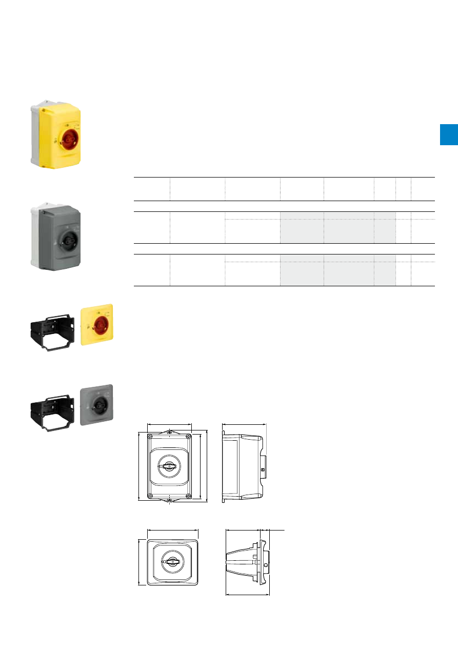
2C
D
C
13
105
0
C0
2
01
ABB
|
2
/23
Description
IB132 are IP65 enclosures for single MMS installation. Additional mounting of auxiliary and signalling
contacts, shunt trips and undervoltage release is possible. The handle is lockable in OFF position. For
detailed specification see installation instruction.
DMS132 are IP65 door mounting kits for MMS installation in any enclosure. Additional mounting of
auxiliary, signalling, shunt trips and undervoltage release is possible. The handle is lockable in OFF
position. For detailed specification see installation instruction.
Ordering details
Suitable for
Description
Color
Type
Order code
Pkg
qty
Weight
(1 pce)
kg
IP65 enclosures (UL: Type 12)
MS116,
MS132, MO132
Padlockable max. 3
padlocks with bail
diameter
4...6.5 mm
Yellow/red
IB132-Y
1
0.370
Grey/black
IB132-G
1
0.370
IP65 door mounting kits (UL: Type 12)
MS116,
MS132, MO132
Padlockable max. 3
padlocks with bail
diameter
4...6.5 mm
Yellow/red
DMS132-Y
1
0.170
Grey/black
DMS132-G
1
0.170
Indication I-O-T and ON-OFF-T.
2CDC241004F0010
IB132-Y
2CDC241003F0010
IB132-G
2CDC241002F0010
DMS132-Y
2CDC241001F0010
DMS132-G
MS116, MS132, MO132 manual motor starters
Main accessories
Main dimensions
mm,
inches
119
4.69"
I ON
0
OFF
183
7.2"
174
6.85"
194
7.64"
118
4.65"
2CDC242011F0011
IB132
121
4.76"
135.7
5.34"
92
3.62"
24
.94"
116.15
4.57"
I ON
0
OFF
2CDC242012F0011
DMS132
2
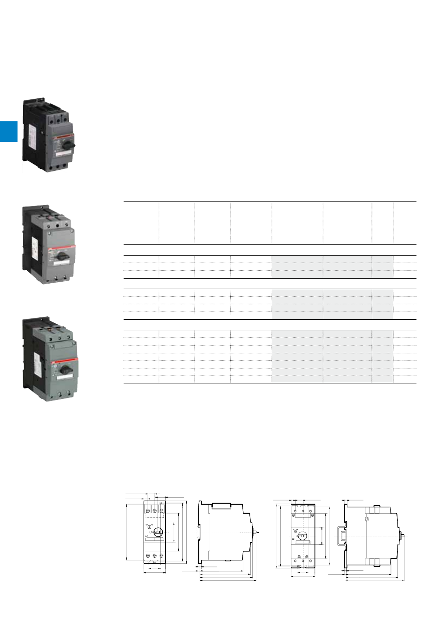
2C
D
C
13
10
42C
0
2
01
2
/24 |
ABB
MS450, MS495, MS497 manual motor starters
22 to 100 A – with thermal and electromagnetic protection
Description
Manual motor starters (MMS) are protection devices for the main circuit. They combine motor control and
protection in a single device. MMS are used mainly to switch motors manually ON/OFF and protect them
and the installation fuse less against short-circuit, overload and phase failures. Fuse less protection with
a manual motor starter saves costs, space and ensures a quick reaction under short-circuit condition, by
switching off the motor within milliseconds.
Further features are the build-in disconnect function, temperature compensation, trip-free mechanism
and a rotary handle with a clear switch position indication. The manual motor starter is suitable for three-
and single-phase applications. The handle is lockable to protect against unauthorized changes. Auxiliary
contacts, signalling contacts, undervoltage releases, shunt trips, three-phase busbars, power in-feed
blocks are available as accessory.
Ordering details
Rated
operational
power
400 V
AC-3
Setting range Short-circuit
breaking
capacity Ics
at 400 V AC
Rated
instantaneous
short-circuit
current setting li
Type
Order code
Weight
(1 pce)
kW
A
kA
A
kg
MS450 manual motor starters
15.8
28.0…40.0
25
520.00
MS450-40
1.047
22
36.0…45.0
25
585.00
MS450-45
1.039
22
40.0…50.0
25
650.00
MS450-50
1.027
MS495 manual motor starters
30
45.0…63.0
25
819.00
MS495-63
2.247
37
57.0…75.0
25
975.00
MS495-75
2.253
45
70.0…90.0
25
1170.00
MS495-90
2.280
55
80.0…100.0
25
1235.00
MS495-100
2.295
MS497 manual motor starters
15
22.0…32.0
50
416.00
MS497-32
2.222
18.5
28.0…40.0
50
520.00
MS497-40
2.203
22
36.0…50.0
50
650.00
MS497-50
2.230
30
45.0…63.0
50
819.00
MS497-63
2.255
37
57.0…75.0
50
975.00
MS497-75
2.266
45
70.0…90.0
50
1170.00
MS497-90
2.268
55
80.0…100.0
50
1235.00
MS497-100
2.275
2CDC241004F0009
MS450-40
1SBC101184F0014
MS495-40
2CDC241020F0011
MS497-100
Main dimensions
mm,
inches
109
127
132
125
85
130
140
45
144
30
55
17
10
20
5
8
4.29"
5.0"
5.2"
4.92"
3.35"
5.12"
5.51"
1.77"
5.67"
1.18"
2.17"
0.67"
0.39"
0.79"
0.20"
0.32"
2CDC242013F0011
132
153
169
155
165
150
116
45
70
8
7
5
30
12
23
6.10"
6.50"
5.91"
4.57"
1.77"
0.31"
0.47"
0.91"
5.20"
6.02"
6.65"
2.56"
0.28"
0.20"
1.18"
2CDC242014F0011
MS450
MS495, MS497
2
2C
D
C
13
10
42C
0
2
01
ABB
|
2
/25
MS450, MS495, MS497 manual motor starters
Technical data
Main circuit – Utilization characteristics according to IEC/EN
Type
MS450, MS495, MS497
Standards
IEC/EN 60947–2, IEC/EN 60947-4-1, IEC/EN 60947-1
Rated operational voltage U
e
690 V AC / 450 V DC
Rated frequency
50/60 Hz
Trip class
10
Number of poles
3
Duty time
100 %
Mechanical durability
50000 cycles
Electrical durability
25000 cycles
Rated impulse withstand voltage U
imp
6 kV
Rated insulation voltage U
i
690 V AC
Rated operational current I
e
See ordering details
Rated instantaneous short-circuit current setting I
i
See ordering details
Rated service short-circuit breaking capacity I
cs
See table "Short-circuit breaking capacity and back-up fuses"
Rated ultimate short-circuit breaking capacity I
cu
See table "Short-circuit breaking capacity and back-up fuses"
Short-circuit breaking capacity and back-up fuses
l
CS
Rated service short-circuit breaking capacity
l
CU
Rated ultimate short-circuit breaking capacity
I
CC
Prospective short-circuit current at installation location
Note: Maximum rated current of the back-up fuses if I
CC
> I
CS
Type
240 V AC
400 V AC
440 V AC
500 V AC
690 V AC
I
CS
kA
I
CU
kA
gG, aM
A
I
CS
kA
I
CU
kA
gG, aM
A
I
CS
kA
I
CU
kA
gG, aM
A
I
CS
kA
I
CU
kA
gG, aM
A
I
CS
kA
I
CU
kA
gG, aM
A
Short-circuit protection MS450
MS450-40
No back-up fuse required up to
I
CC
= 100 kA
25
50
160
15
50
125
5
10
100
2
4
63
MS450-45
25
50
160
15
50
125
5
10
100
2
4
63
MS450-50
25
50
160
15
50
125
5
10
100
2
4
80
MS450:
No need for back-up fuse in networks with a prospective current of up to 50 kA at 400 V.
With an approbiate 160 A type gG fuse the device can be used in a network with a prospective current of up to 100 kA.
Short-circuit protection MS495
MS495-40
No back-up fuse required up to
I
CC
= 100 kA
25
50
125
20
50
125
6
12
125
3
6
63
MS495-50
25
50
125
20
50
125
6
12
125
3
6
80
MS495-63
25
50
160
20
50
160
6
12
160
3
6
80
MS495-75
25
50
160
20
50
160
6
8
160
3
5
100
MS495-90
25
50
160
20
50
160
6
8
160
3
5
125
MS495-100
25
50
160
20
50
160
6
8
160
3
5
125
MS495-40: No need for back-up fuse in networks with a prospective current of up to 50 kA at 400 V.
With an approbiate 125 A type gG fuse the device can be used in a network with a prospective current of up to 100 kA.
MS495-100: No need for back-up fuse in networks with a prospective current of up to 50 kA at 400 V.
With an approbiate 160 A type gG fuse the device can be used in a network with a prospective current of up to 100 kA.
Short-circuit protection MS497
MS497-32
No back-up fuse required up to
I
CC
= 100 kA
50
100
No back-
up fuse
required
up to I
CC
= 100 kA
50
100
No back-up
fuse required
up to
I
CC
= 100 kA
11
22
100
7
12
63
MS497-40
50
100
50
100
9
18
160
6
12
80
MS497-50
50
100
50
100
7.5
15
160
5
10
100
MS497-63
50
100
50
70
200
7.5
15
160
4
7.5
100
MS497-75
50
100
50
70
200
5
10
160
3
6
125
MS497-90
50
100
50
70
200
5
10
160
3
6
160
MS497-100
50
100
50
70
200
5
10
160
3
6
160
MS497-32: No need for back-up fuse in networks with a prospective current of up to 100 kA at 440 V.
MS497-90: No need for back-up fuse in networks with a prospective current of up to 70 kA at 440 V.
With an approbiate 200 A type gG fuse the device can be used in a network with a prospective current of up to 100 kA.
2
2C
D
C
13
10
42C
0
2
01
2
/26 |
ABB
MS450, MS495, MS497 manual motor starters
Technical data
Main circuit – Utilization characteristics according to UL/CSA
Type
MS450, MS495, MS497
Standards
UL 508, CSA 22.2 No. 14
Maximum operational voltage
600 V AC
Manual motor controller ratings
See table "UL 508 – Manual motor controller"
Trip rating
125 % FLA
Motor ratings
Horse power
See table "Motor rating, three phase"
Full load amps (FLA)
See table "Motor rating, three phase"
Locked rotor amps (LRA)
See table "Motor rating, three phase"
Motor rating, three phase
hp
Horse power
FLA Full load amps
LRA Locked rotor amps
Type
General purpose rating
at max. 600 V AC
Full load amps
200 - 208 V AC
230 V AC
460 V AC
575 V AC
A
FLA
hp
hp
hp
hp
MS450-40
40
40
10
15
30
40
MS450-45
45
45
15
15
30
40
MS450-50
50
50
15
20
40
50
MS495-63
63
63
20
25
50
60
MS495-75
75
75
25
25
60
75
MS495-90
90
90
30
30
75
100
MS495-100
100
100
40
40
75
100
MS497-32
32
32
10
10
25
30
MS497-40
40
40
15
15
30
40
MS497-50
50
50
15
20
40
50
MS497-63
63
63
20
25
50
60
MS497-75
75
75
25
25
60
75
MS497-90
90
90
30
30
75
100
MS497-100
100
100
30
40
75
100
UL 508 – Manual motor controller
Type
Circuit breaker
or class R fuse
per UL/NEC
Max. circuit
breaker or
fuse per UL/
NEC
Maximum short-circuit current
for motor disconnect
for group installation
for tap
conductor
for protection UL 508
Type E *
Type E
480/600 V
A
480/600 V
A
480 V
kA
600 V
kA
480 V
kA
600 V
kA
480Y/277V
kA
600Y/347V
kA
480Y/277V
kA
600Y/347V
kA
MS450-40
150
350
65
25
65
25
65
25
65
25
MS450-45
175
350
65
25
65
25
65
25
65
25
MS450-50
200
350
65
25
65
25
65
25
65
25
MS495-63
250
500
65
30
65
30
65
30
65
30
MS495-75
300
500
65
30
65
30
65
30
65
30
MS495-90
350
500
65
10
65
10
65
-
65
-
MS495-100
400
500
65
10
65
10
65
-
65
-
MS497-32
120
500
65
30
65
30
65
30
65
30
MS497-40
160
500
65
30
65
30
65
30
65
30
MS497-50
200
500
65
30
65
30
65
30
65
30
MS497-63
250
500
65
30
65
30
65
30
65
30
MS497-75
300
500
65
30
65
30
65
30
65
30
MS497-90
350
500
65
10
65
10
-
-
65
-
MS497-100
400
500
65
10
65
10
-
-
65
-
* only with use DX495
2
2C
D
C
13
10
42C
0
2
01
ABB
|
2
/27
General technical data
Type
MS450
MS495
MS497
Pollution degree
3
Phase loss sensitivity
Yes
Disconnect function acc. to IEC/EN 60947-2
Yes
Ambient air temperature
Operation
Open - compensated
-20 ... +60 °C
Open
-20 ... +70 °C
Enclosed
-20 ... +35 °C
Storage
-50 ... +80 °C
Ambient air temperature compensation
Acc. to IEC/EN60947-4-1
Maximum operating altitude permissible
2000 m
Resistance to shock acc. to IEC 60068-2-27
25g / 11 ms
-
Resistance to vibrations acc. to IEC 60068-2-6
2g / 5-150 Hz
Mounting position
Position 1-6 (optional for single mounting)
Mounting
DIN-rail 35 mm (EN 60715)
DIN-rail 15 mm / 75 mm (EN 60715)
Minimum distance to other
units same type
Horizontal
0 mm
0 mm
Vertical - up to 240 V
-
50 mm
Vertical - up to 440 V
-
70 mm
Vertical - up to 500 V
-
110 mm
Vertical - up to 690 V
-
150 mm
Vertical
50 mm
-
Minimum distance to
electrical conductive board
Horizontal
10 mm
-
Horizontal - up to 500 V
-
10 mm
Horizontal - up to 690 V
-
30 mm
Vertical - up to 240 V
-
50 mm
Vertical - up to 440 V
-
70 mm
Vertical - up to 500 V
-
110 mm
Vertical - up to 690 V
-
150 mm
Vertical
50 mm
-
Degree of protection
Housing
IP20
Main circuit terminals
IP00
Connecting characteristics
Main circuit
Type
MS450
MS495
MS497
Connecting capacity
Rigid
1 or 2 x
0.75 ... 16 mm²
2.5 ... 16 mm²
2.5 ... 16 mm²
Flexible with ferrule
1 x
2 x
0.75 ... 35 mm²
0.75 ... 25 mm²
10 ... 70 mm²
10 ... 50 mm²
10 ... 70 mm²
10 ... 50 mm²
Flexible
1 x
2 x
0.75 ... 35 mm²
0.75 ... 25 mm²
10 ... 70 mm²
10 ... 50 mm²
10 ... 70 mm²
10 ... 50 mm²
Stranded acc. to UL/CSA
1 x
2 x
AWG 18-2
AWG 18-2
AWG 10-2/0
AWG 10-1/0
AWG 10-2/0
AWG 10-1/0
Flexible acc. to UL/CSA
1 x
2 x
AWG 18-2
AWG 18-2
AWG 10-2/0
AWG 10-1/0
AWG 10-2/0
AWG 10-1/0
Stripping length
13 mm
17 mm
17 mm
Tightening torques
3 - 4.5 Nm / 27 … 40 Ib.in
4 - 6 Nm / 35 - 53 Ib.in
4 - 6 Nm / 35 - 53 Ib.in
Connection screw
Pozidriv 2
Hexagon 4
Hexagon 4
MS450, MS495, MS497 manual motor starters
Technical data
2
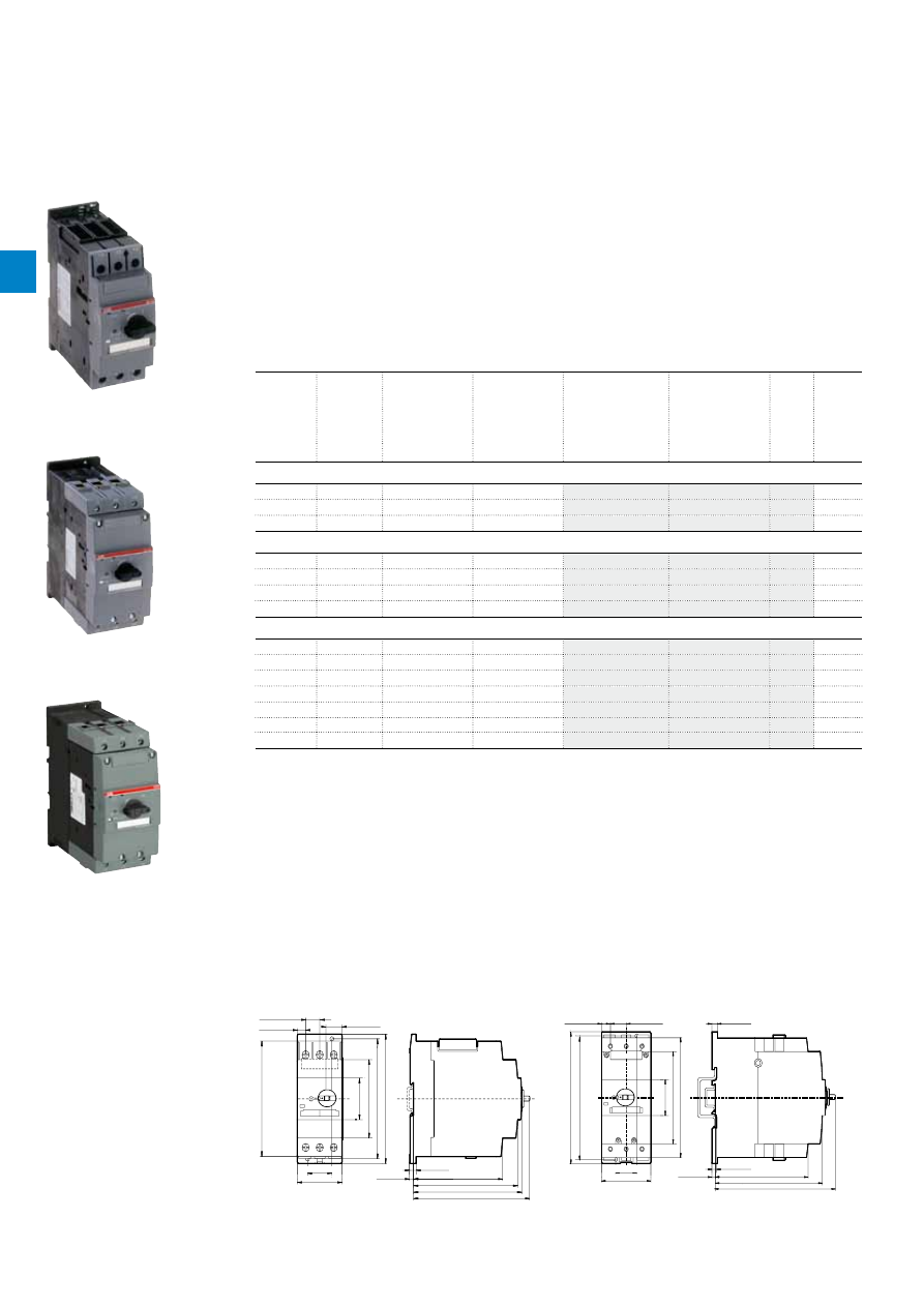
2CD
C
13
10
38
C
0
2
01
2
/28 |
ABB
MO450, MO495, MO496 manual motor starters magnetic only
32 to 100 A – with electromagnetic protection
Description
The manual motor starter magnetic only is used to manually switch on and off motors and to protect them
reliably and without the need for a fuse from short-circuits.
Further features are the build-in disconnect function, trip-free mechanism and a rotary handle with a
clear switch position indication. The manual motor starter magnetic only is suitable for three- and single-
phase applications. The handle is lockable to protect against unauthorized changes. Auxiliary contacts,
signalling contacts, undervoltage releases, shunt trips, three-phase busbars, power in-feed blocks are
available as accessory.
Ordering details
Rated
operational
power
400 V
AC-3
(1)
Rated
operational
current
Short-circuit
breaking
capacity Ics at
400 V AC
Rated
instantaneous
short-circuit
current setting li
Type
Order code
Weight
(1 pce)
kW
A
kA
A
kg
MO450 manual motor starter magnetic only
15.8
40
25
520.00
MO450-40
1.033
22
45
25
585.00
MO450-45
1.040
22
50
25
650.00
MO450-50
1.019
MO495 manual motor starter magnetic only
30
63
25
819.00
MO495-63
2.244
37
75
25
975.00
MO495-75
2.247
45
90
25
1170.00
MO495-90
2.269
55
100
25
1235.00
MO495-100
2.292
MO496 manual motor starter magnetic only
15
32
50
416.00
MO496-32
2.208
18.5
40
50
520.00
MO496-40
2.218
22
50
50
650.00
MO496-50
2.218
30
63
50
819.00
MO496-63
2.248
37
75
50
975.00
MO496-75
2.278
45
90
50
1170.00
MO496-90
2.266
55
100
50
1235.00
MO496-100
2.293
(1) For overload protection of motors, an appropriate thermal or electronic overload relay must be used.
ST02501
MO450-40
ST02601
MO495-75
2CDC241021F0011
MO496-100
Main dimensions
mm,
inches
109
127
132
125
85
130
140
45
144
55
17
10
20
5
8
4.92"
3.35"
5.12"
5.51"
1.77"
4.29"
5.0"
5.2"
5.67"
1.18"
30
2.17"
0.67"
0.39"
0.79"
0.20"
0.32"
2CDC242015F0011
132
153
169
155
165
150
116
45
70
8
7
5
30
12
23
6.10"
6.50"
5.91"
4.57"
1.77"
5.20"
6.02"
6.65"
2.56"
0.31"
0.28"
0.20"
1.18"
0.47"
0.91"
2CDC242016F0011
MO450
MO495, MO496
2
2CD
C
13
10
38
C
0
2
01
ABB
|
2
/29
MO450, MO495, MO496 manual motor starters magnetic only
Technical data
Main circuit – Utilization characteristics according to IEC/EN
Type
MO450, MO495, MO496
Standards
IEC/EN 60947–2, IEC/EN 60947-4-1, IEC/EN 60947-1
Rated operational voltage U
e
690 V AC / 450 V DC
Rated frequency
50/60 Hz
Number of poles
3
Duty time
100 %
Mechanical durability
50000 cycles
Electrical durability
25000 cycles
Rated impulse withstand voltage U
imp
6 kV
Rated insulation voltage U
i
690 V AC
Rated operational current I
e
See ordering details
Rated instantaneous short-circuit current setting I
i
See ordering details
Rated service short-circuit breaking capacity I
cs
See table "Short-circuit breaking capacity and back-up fuses"
Rated ultimate short-circuit breaking capacity I
cu
See table "Short-circuit breaking capacity and back-up fuses"
Short-circuit breaking capacity and back-up fuses
l
CS
Rated service short-circuit breaking capacity
l
CU
Rated ultimate short-circuit breaking capacity
I
CC
Prospective short-circuit current at installation location
Note: Maximum rated current of the back-up fuses if I
CC
> I
CS
Type
240 V AC
400 V AC
440 V AC
500 V AC
690 V AC
I
CS
kA
I
CU
kA
gG, aM
A
I
CS
kA
I
CU
kA
gG, aM
A
I
CS
kA
I
CU
kA
gG, aM
A
I
CS
kA
I
CU
kA
gG, aM
A
I
CS
kA
I
CU
kA
gG, aM
A
Short-circuit protection MO450
MO450-40
No back-up fuse required up to
I
CC
= 100 kA
25
50
160
15
50
125
5
10
100
2
4
63
MO450-45
25
50
160
15
50
125
5
10
100
2
4
63
MO450-50
25
50
160
15
50
125
5
10
100
2
4
80
MO450:
No need for back-up fuse in networks with a prospective current of up to 50 kA at 400 V.
With an approbiate 160 A type gG fuse the device can be used in a network with a prospective current of up to 100 kA.
Short-circuit protection MO495
MO495-63
No back-up fuse required up to
I
CC
= 100 kA
25
50
160
20
50
160
6
12
160
3
6
80
MO495-75
25
50
160
20
50
160
6
8
160
3
5
100
MO495-90
25
50
160
20
50
160
6
8
160
3
5
125
MO495-100
25
50
160
20
50
160
6
8
160
3
5
125
MO495-100: No need for back-up fuse in networks with a prospective current of up to 50 kA at 400 V.
With an approbiate 160 A type gG fuse the device can be used in a network with a prospective current of up to 100 kA.
Short-circuit protection MO496
MO496-32
No back-up fuse required up to
I
CC
= 100 kA
50
100
No back-
up fuse
required
up to I
CC
= 100 kA
50
100
No back-up
fuse required
up to
I
CC
= 100 kA
11
22
100
7
12
63
MO496-40
50
100
50
100
9
18
160
6
12
80
MO496-50
50
100
50
100
7.5
15
160
5
10
100
MO496-63
50
100
50
70
200
7.5
15
160
4
7.5
100
MO496-75
50
100
50
70
200
5
10
160
3
6
125
MO496-90
50
100
50
70
200
5
10
160
3
6
160
MO496-100
50
100
50
70
200
5
10
160
3
6
160
MO496-32: No need for back-up fuse in networks with a prospective current of up to 100 kA at 440 V.
MO496-90: No need for back-up fuse in networks with a prospective current of up to 70 kA at 440 V.
With an approbiate 200 A type gG fuse the device can be used in a network with a prospective current of up to 100 kA.
2
2CD
C
13
10
38
C
0
2
01
2
/30 |
ABB
MO450, MO495, MO496 manual motor starters magnetic only
Technical data
Main circuit – Utilization characteristics according to UL/CSA
Type
M0450, MO495, MO496
Standards
UL 508, CSA 22.2 No. 14
Maximum operational voltage
600 V AC
Manual motor controller ratings
See table "UL 508 – Manual motor controller"
Trip rating
125 % FLA
Motor ratings
Horse power
See table "Motor rating, three phase"
Full load amps (FLA)
See table "Motor rating, three phase"
Locked rotor amps (LRA)
See table "Motor rating, three phase"
Motor rating, three phase
hp
Horse power
FLA Full load amps
LRA Locked rotor amps
Type
General purpose rating
at max. 600 V AC
Full load amps
200 - 208 V AC
230 V AC
460 V AC
575 V AC
A
FLA
hp
hp
hp
hp
MO450-40
40
40
10
15
30
40
MO450-45
45
45
15
15
30
40
MO450-50
50
50
15
20
40
50
MO495-63
63
63
20
25
50
60
MO495-75
75
75
25
25
60
75
MO495-90
90
90
30
30
75
100
MO495-100
100
100
40
40
75
100
MO496-32
32
32
10
10
25
30
MO496-40
40
40
15
15
30
40
MO496-50
50
50
15
20
40
50
MO496-63
63
63
20
25
50
60
MO496-75
75
75
25
25
60
75
MO496-90
90
90
30
30
75
100
MO496-100
100
100
30
40
75
100
UL 508 – Manual motor controller
Type
Circuit breaker or class R
fuse per UL/NEC
Max. circuit breaker or
fuse per UL/NEC
Maximum short-circuit current
for motor disconnect
for group installation
480/600 V
A
480/600 V
A
480 V
kA
600 V
kA
480 V
kA
600 V
kA
MO450-40
150
-
65
25
65
25
MO450-45
175
-
65
25
65
25
MO450-50
200
-
65
25
65
25
MO495-63
60
500
65
30
65
30
MO495-75
250
500
65
30
65
30
MO495-90
300
500
65
30
65
30
MO495-100
350
500
65
10
65
10
MO496-32
120
500
65
30
65
30
MO496-40
160
500
65
30
65
30
MO496-50
200
500
65
30
65
30
MO496-63
250
500
65
30
65
30
MO496-75
300
500
65
30
65
30
MO496-90
350
500
65
10
65
10
MO496-100
400
500
65
10
65
10
* only with use DX495
2

2CD
C
13
10
38
C
0
2
01
ABB
|
2
/31
General technical data
Type
MO450
MO495
MO496
Pollution degree
3
Phase loss sensitivity
No
Disconnect function acc. to IEC/EN 60947-2
Yes
Ambient air temperature
Operation
Open - compensated
-20 ... +60 °C
Open
-20 ... +70 °C (above 60° C, current derating)
Enclosed
-20 ... +35 °C
Storage
-50 ... +80 °C
Ambient air temperature compensation
-
Maximum operating altitude permissible
2000 m
Resistance to shock acc. to IEC 60068-2-27
25g / 11 ms
Resistance to vibrations acc. to IEC 60068-2-6
2g / 5-150 Hz
-
Mounting position
Position 1-6 (optional for single mounting)
Mounting
DIN-rail 35 mm (EN 60715)
DIN-rail 15 mm / 75 mm (EN 60715)
Minimum distance to other
units same type
Horizontal
0 mm
0 mm
Vertical - up to 240 V
-
50 mm
Vertical - up to 440 V
-
70 mm
Vertical - up to 500 V
-
110 mm
Vertical - up to 690 V
-
150 mm
Vertical
50 mm
-
Minimum distance to
electrical conductive board
Horizontal
10 mm
-
Horizontal - up to 500 V
-
10 mm
Horizontal - up to 690 V
-
30 mm
Vertical - up to 240 V
-
50 mm
Vertical - up to 440 V
-
70 mm
Vertical - up to 500 V
-
110 mm
Vertical - up to 690 V
-
150 mm
Vertical
50 mm
-
Degree of protection
Housing
IP20
Main circuit terminals
IP20
Connecting characteristics
Main circuit
Type
MO450
MO495
MO496
Connecting capacity
Rigid
1 or 2 x
0.75 ... 16 mm²
2.5 ... 16 mm²
2.5 ... 16 mm²
Flexible with ferrule
1 x
2 x
0.75 ... 35 mm²
0.75 ... 25 mm²
10 ... 70 mm²
10 ... 50 mm²
10 ... 70 mm²
10 ... 50 mm²
Flexible
1 x
2 x
0.75 ... 35 mm²
0.75 ... 25 mm²
10 ... 70 mm²
10 ... 50 mm²
10 ... 70 mm²
10 ... 50 mm²
Stranded acc. to UL/CSA
1 x
2 x
AWG 18-2
AWG 18-2
AWG 10-2/0
AWG 10-1/0
AWG 10-2/0
AWG 10-1/0
Flexible acc. to UL/CSA
1 x
2 x
AWG 18-2
AWG 18-2
AWG 10-2/0
AWG 10-1/0
AWG 10-2/0
AWG 10-1/0
Stripping length
13 mm
17 mm
17 mm
Tightening torques
3 - 4.5 Nm / 27 … 40 Ib.in
4 - 6 Nm / 35 - 53 Ib.in
4 - 6 Nm / 35 - 53 Ib.in
Connection screw
Pozidriv 2
Hexagon 4
Hexagon 4
MO450, MO495, MO496 manual motor starters magnetic only
Technical data
2

2C
D
C
13
105
1C0
2
01
2
/32 |
ABB
MS45x, MS49x, MO45x, MO49x manual motor starters
Main accessories
MO45x and MO49x manual motor starters with accessories
MS45x
MS49x
HKS4
HKS4
SK4
SK4
UA4-HK
UA4/AA4
HK4
MO45x
MO49x
HKS4
HKS4
SK4
SK4
UA4-HK
UA4/AA4
HK4
MS45x and MS49x manual motor starters with accessories
2CDC242025F0011
2CDC242025F0011
2
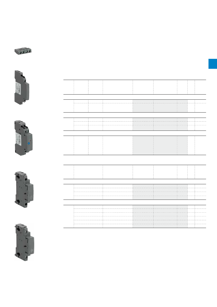
2C
D
C
13
105
1C0
2
01
ABB
|
2
/33
MS45x, MS49x, MO45x, MO49x manual motor starters
Main accessories
Description
Manual motor starters can be equipped with auxiliary contacts for lateral/front mounting, signalling contact
for lateral mounting, undervoltage release and shunt trips. The accessories can be fitted wiring free and
without tools. A variety of combinations is possible as required for the application. The auxiliary contacts
change position with the main contacts. Undervoltage release are used for remote tripping of the manual
motor starter especially for emergency stop circuits. Shunt trips release the MMS used for remote tripping.
Ordering details
Suitable
for
Auxiliary
contacts
N.O.
Auxiliary
contacts
N.C.
Description
Type
Order code
Pkg
qty
Weight
(1 pce)
kg
Auxiliary contacts – mountable on the front
MS45x,
MS49x,
MO45x,
MO49x
1
1
HK4-11
10
0.017
Changeover
HK4-W
10
0.015
Auxiliary contacts – mountable on the left
MS45x,
MS49x,
MO45x,
MO49x
1
1
Max. 1 piece
HKS4-11
2
0.045
2
0
Max. 1 piece
HKS4-20
2
0.045
0
2
Max. 1 piece
HKS4-02
2
0.045
Signalling contacts – mountable on the left
MS45x,
MS49x,
MO45x,
MO49x
2
2
Separate signalling acc.
UL508E 1 N.O.
+ 1 N.C. for short circuit
alarm and 1 N.O. + 1 N.C.
for tripped alarm, max.
1x SK4-11 + 1 x HKS4-xx
SK4-11
1
0.093
Suitable
for
Rated control supply
voltage
Frequency
Type
Order code
Pkg
qty
Weight
(1 pce)
V
Hz
kg
Shunt trip units – mountable on the right
MS45x,
MS49x,
MO45x,
MO49x
20...24
50/60
AA4-24
1
0.135
90...110
50/60
AA4-110
1
0.135
200...240
50/60
AA4-230
1
0.128
350...415
50/60
AA4-400
1
0.125
Undervoltage releases – mountable on the right
MS45x,
MS49x,
MO45x,
MO49x
24
50/60
UA4-24
1
0.134
110/120
50/60
UA4-110
1
0.134
230/240
50/60
UA4-230
1
0.131
400/440
50/60
UA4-400
1
0.129
230/240
50/60
UA4-HK-230
1
0.140
400/440
50/60
UA4-HK-400
1
0.137
2CDC241026F0011
HK4-11
2CDC241022F0011
HKS4-20
2CDC241024F0011
SK4-11
2CDC241023F0011
AA4-24
2CDC241025F0011
UA4-110
2

2C
D
C
13
105
1C0
2
01
2
/34 |
ABB
MS45x, MS49x, MO45x, MO49x manual motor starters
Main accessories
General technical data
Type
HK4-11
HK4-W
HKS4
SK4
Standards
IEC/EN 60947–1, IEC/EN 60947-5-1, UL 508, CSA22.2 No. 14
Rated operational voltage U
e
230 V AC / 220 V DC
690 V AC / 220 V DC
690 V AC
690 V AC
Conventional free-air thermal current I
th
2.5 A
5 A
10 A
10 A
Rated frequency
DC, 50/60 Hz
Rated impulse withstand voltage U
imp
6 kV
Rated insulation voltage U
i
300 V
300 V
690 V
690 V
Pollution degree
3
Ambient air temperature
Operation
-20 ... +70 °C
Storage
-50 ... +80 °C
Resistance to shock acc. to IEC 60068-2-27
25g / 11 ms
Resistance to vibrations acc. to IEC 60068-2-6
2g / 5 ... 150 Hz
Number of poles
1 N.C. + 1 N.O.
Changeover
1 N.C. + 1 N.O. /
2 N.O. / 2 N.C.
2 N.C. + 2 N.O.
I
e
/ Rated operational current AC-15
acc. to IEC/EN 60947-5-1 for utilization category
24 V
2 A
4 A
6 A
6 A
230 V
0.5 A
3 A
4 A
4 A
400 V
-
1.5 A
3 A
3 A
690 V
-
0.5 A
1 A
1 A
I
e
/ Rated operational current DC-13
acc. to IEC/EN 60947-5-1 for utilization category
24 V
1 A
1 A
2 A
2 A
48 V
0.3 A
-
-
-
60 V
0.15 A
-
-
-
110 V
-
0.22 A
0.5 A
0.5 A
230 V
-
0.1 A
0.25 A
0.25 A
Minimum switching capacity
17 V / 1 mA
-
-
Short-circuit protective device
10 A Type gG
Duty time
100 %
Mounting
Front of MMS
Front of MMS
Left side of MMS
Left side of MMS
Mounting positions
1-6
Mechanical durability
100000 cycles
Electrical durability
100000 cycles
Type
UA4-xxx
AA4-xxx
Power consumption
Pull-in
AC
20.2/13 VA/W
20.2/13 VA/W
DC
20 W
13 … 80 W
Holding
AC
7.2/2.4 VA/W
-
DC
2.1 W
-
Operating voltage
Tripping
0.35 … 0.7 V x U
s
0.7 … 1.1 V x U
s
Coil operating voltage
0.85 … 1.1 V x U
s
-
2
2C
D
C
13
105
1C0
2
01
ABB
|
2
/35
Connecting characteristics
Auxiliary circuit
Type
HK4-11
HK4-W
HKS4
SK4
Connecting capacity
Rigid
1 x
2 x
0.5... 2.5 mm²
0.5 ... 1.5 mm² or 0.75 ... 2.5 mm
Flexible with ferrule
1 x
2 x
0.5 ... 2.5 mm²
0.5 ... 1.5 mm² or 0.75 ... 2.5 mm
Flexible
1 x
2 x
0.5 ... 2.5 mm²
0.5 ... 1.5 mm² or 0.75 ... 2.5 mm
Flexible
1 x
2 x
0.5 ... 2.5 mm²
0.5 ... 1.5 mm² or 0.75 ... 2.5 mm
Stranded acc. to UL/CSA
1 or 2 x
AWG 18-14
Flexible acc. to UL/CSA
1 or 2 x
AWG 18-14
Stripping length
10 mm
Tightening torques
0.8 ... 1.2 Nm / 7 ... 10.3 Ib.in
Connection screw
Pozidriv 2
MS45x, MS49x, MO45x, MO49x manual motor starters
Main accessories
2
2C
D
C
13
105
1C0
2
01
2
/36 |
ABB
MS45x, MS49x, MO45x, MO49x manual motor starters
Main accessories
Description
Three-phase busbars ensure a quick and safe connection and are therefor a cost effective solution.
A variety of different three-phase busbars up to 108 A are in the assortment. Between 2 and 4 manual
motor starter with none or two lateral auxiliary contacts can be connected.
Ordering details
Suitable for
Rated
operational
current
Number of
MMS
Number of
lateral aux.
Type
Order code
Pkg
qty
Weight
(1 pce)
A
kg
Three-phase busbars
MS450, MO450 108 A
2
0
PS4-2-0
5
0.134
108 A
3
0
PS4-3-0
5
0.206
108 A
4
0
PS4-4-0
5
0.280
108 A
2
1
PS4-2-2
5
0.148
108 A
3
1
PS4-3-2
5
0.250
108 A
4
1
PS4-4-2
5
0.362
Suitable for
Rated
operational
current
Rated cross
section
Mounting
form
Type
Order code
Pkg
qty
Weight
(1 pce)
A
mm²
kg
Three-phase feeder terminals
MS450, MO450 108 A
25
Flat
S4-M1
2
0.106
Suitable for
Description
Type
Order code
Pkg
qty
Weight
(1 pce)
kg
MS450, MO450
Protection cover for busbar
BS4-3
10
0.001
Disconnector module
TB450
1
0.315
Terminal shroud
KA450
1
0.154
MS495, MS497,
MO495, MO496
Terminal shroud
KA495
10
0.018
Terminal shroud
KA495C (1)
10
0.038
Terminal insulation barrier for
UL508E
DX495
1
0.154
MS450, MS495, MS497, MO450,
MO495, MO496
Padlock + two keys
SA2
10
0.020
(1) Is plugged onto the housing after removing the box terminals, if using cable lugs.
2CDC241003F0012
PS4-2-0
2CDC241004F0012
PS4-3-0
2CDC241005F0012
PS4-4-0
2CDC241023F0013
SA2
2
2C
D
C
13
105
1C0
2
01
ABB
|
2
/37
MS45x, MS49x, MO45x, MO49x manual motor starters
Main accessories
General technical data
Type
PS4-xxx
S4-M1
Standards
IEC/EN 60947-1
Rated operational voltage U
e
690 V AC
Rated operational current I
e
108 A
Rated frequency
50/60 Hz
Rated impulse withstand voltage U
imp
6 kV
Rated insulation voltage U
i
690 V AC
Pollution degree
3
Cross-section
10 mm²
25 mm²
Ambient air temperature
Operation
-25 ... +70 °C
Storage
-50 ... +80 °C
Connecting characteristics
Main circuit
Type
S4-M1
Connecting capacity
Rigid
1 x
2.5 ... 50 mm²
Flexible with ferrule
1 x
4 ... 16 mm²
Flexible
1 x
4 ... 16 mm²
Stranded acc. to UL/CSA
1 x
AWG 14-4
Flexible acc. to UL/CSA
1 x
AWG 14-4
Tightening torques
4 Nm
Connection screw
Pozidriv 2
2
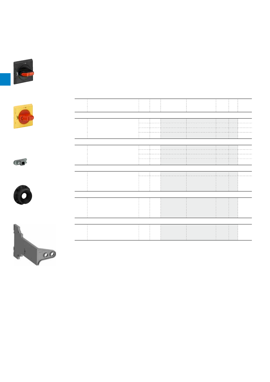
2C
D
C
13
105
3
C0
2
01
2
/38 |
ABB
MS116, MS132, MO132, MS4xx, MO4xx manual motor starters
General accessories
Description
With this solution of door coupling rotary mechanism it is possible to operate a Manual Motor Starter in
the back of a switch cabinet from outside. The door coupling mechanism prevents opening of the door of
a switch cabinet with the Manual Motor Starter in ON position.
The complete mechanism includes handle, shaft, driver, shaft alignment ring and shaft supporter.
All accessories fit for 6 mm shafts with a maximum length of 180 mm. The degree of protection for
handles MSHD is IP64.
Ordering details
Suitable
for
Description
Shaft
length
Color Type
Order code
Pkg
qty
Weight
(1 pce)
mm
kg
Shafts
MS116,
MS132,
MO132,
MS4xx,
MO4xx
For MSHD handles. Shaft diameter
6 mm. Shaft extension for door
coupling driver.
85
OXS6X85
1
0.020
105
OXS6X105
1
0.020
130
OXS6X130
1
0.030
180
OXS6X180
1
0.040
IP64 handles (UL: Type 1, 3R, 12)
MS116,
MS132,
MO132,
MS4xx,
MO4xx
Padlockable max. 3 padlocks with bail
diameter 5 … 8 mm, door interlock in
ON position defeatable, for use with
6 mm OXS6…types up to 180 mm or
driver shafts MSOX.
Black
MSHD-LB (1)
1
0.065
Yellow MSHD-LY (1)
1
0.065
Black
MSHD-LTB (2)
1
0.065
Yellow MSHD-LTY (2)
1
0.065
Driver
MS116,
MS132,
MO132,
MS4xx,
MO4xx
Coupling driver for use with 6 mm
OXS6… types up to 180 mm.
MSMN (3)
1
0.002
MSMNO (4)
1
0.002
Shaft alignment ring
MS116,
MS132,
MO132,
MS4xx,
MO4xx
The MSH-AR supports the long shafts
for alignment to the handle inlet. It
makes closing panel doors more easy.
Use for OXS6X > 105 mm.
MSH-AR
1
0.010
Shaft supporter
MS116,
MS132,
MO132
With the MSAH it is possible to
support the shaft in the extension of
handle (MSHD). It is mandatory for the
usage of shafts >130 mm.
MSAH1
1
0.035
(1) Indication I-O and ON-OFF (recommended for MS116, MS4xx, MO4xx).
(2) Indication I-O and ON-OFF + Trip indication.
(3) Coded - Positioning of ON indication dependent from mounting orientation of the MMS.
(4) Uncoded - Positioning of ON indication independent from mounting orientation of the MMS.
2CDC241003F0011
MSHD-LB
2CDC241002S0011
MSHD-LY
2CDC241004F0011
MSMN
2CDC241001F0012
MSH-AR
2CDC241017V0013
MSAH1
2
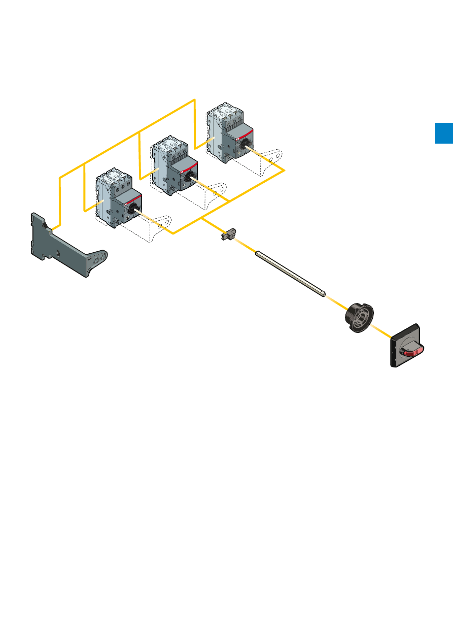
2C
D
C
13
105
3
C0
2
01
ABB
|
2
/39
MS116, MS132, MO132, MS4xx, MO4xx manual motor starters
General accessories
OXS6X
MSHD
MSAH1
MSH-AR
MSMN
MSMNO
2CDC242022F0013
MSAH1
OXS6X
MSMN
MSMNO
MSH-AR
MSHD
2
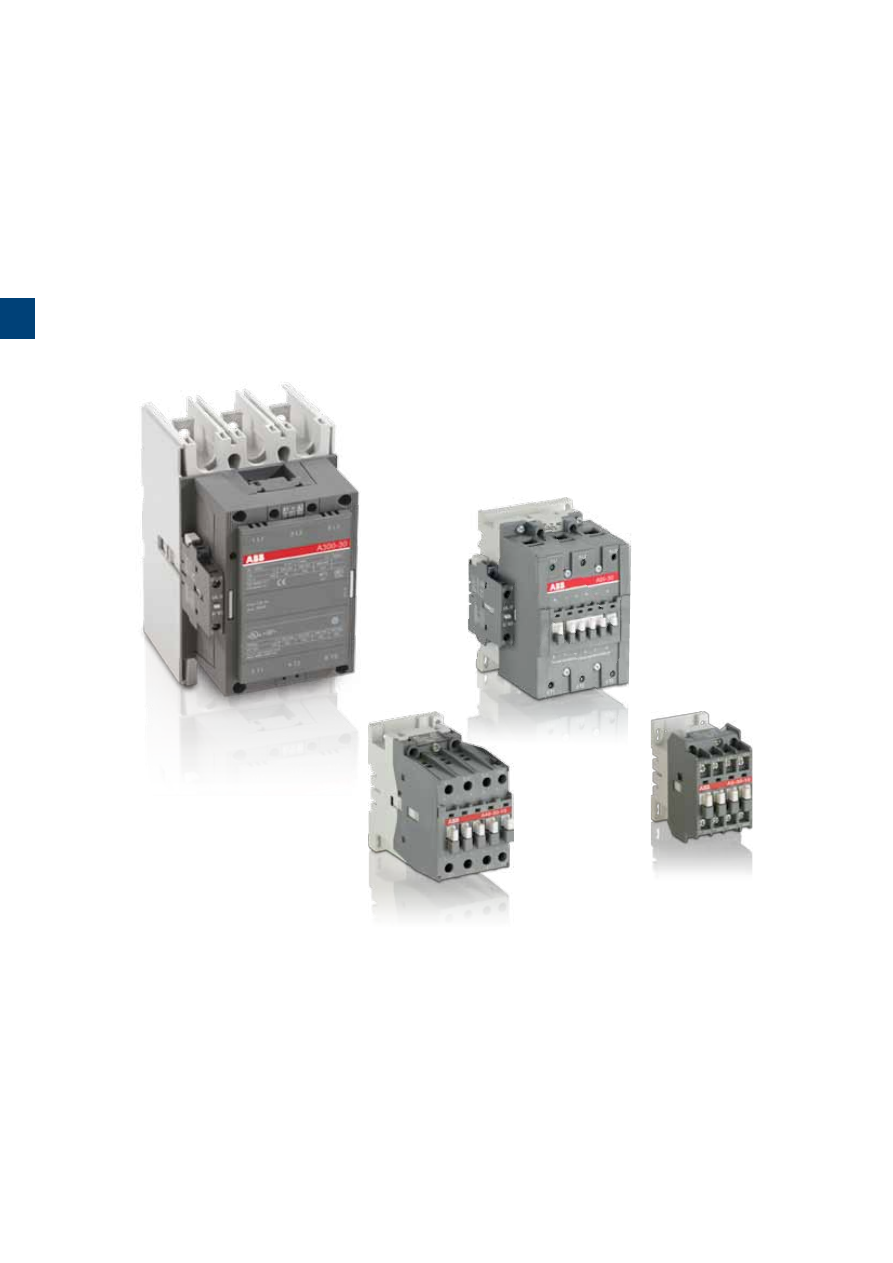
S
umma
ry
_3
3
/0 |
ABB
3

S
umma
ry
_3
ABB
|
3
/1
A contactors and N contactor relays
Terminal marking and positioning
Star-delta starting of three-phase asynchronous motors
Terminal marking and positionning
Terminal marking and positioning
Accessories for A contactors and N contactor relays
Mechanical and electrical interlock units
Electronic timers for star-delta starters
Surge suppressors for contactor coils
Function markers - Impulse contact blocks
Terminal shrouds, terminal enlargements, terminal extensions,
connector terminals
3
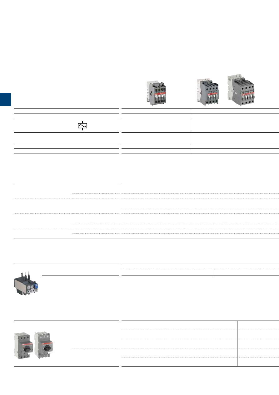
IEC
(1)
AC-3 Rated operational power
θ
≤ 55 °C, 400 V
kW
4
5.5
7.5
11
15
18.5
22
30
37
45
55
75
90
110
140
160
UL/CSA 3-phase motor rating
480 V
hp
5
7.5
10
20
25
30
40
60
60
60
75
100
125
150
200
250
AC Control supply
Type
A9
A12
A16
A26
A30
A40
A50
A63
A75
A95
A110
A145
A185
A210
A260
A300
IEC
AC-3 Rated operational current
θ
≤ 55 °C , 400 V
A
9
12
17
26
32
37
50
65
75
96
110
145
185
210
260
305
AC-1 Rated operational current
θ
≤ 40 °C, 690 V
A
25
27
30
45
55
60
100
115
125
145
160
250
275
350
400
500
UL/CSA General use rating
600 V
A
21
25
30
40
50
60
80
90
105
125
150
230
250
300
350
400
NEMA
NEMA Size
00
0
—
1
1P
—
2
—
3
—
—
4
—
—
5
—
(1) 1000 V IEC ratings available for A50 ... A300 contactors.
Main accessories
Auxiliary contact blocks
Front mounting
CA5-10
(1 x N.O.)
CA5-01
(1 x N.C.)
Side mounting
CAL5-11
(1 x N.O. + 1 x N.C.)
CAL18-11
(1 x N.O. + 1 x N.C.)
Timers
Electronic
TEF5-ON
TEF5-OFF
TE5S
(for star-delta starters - direct timing - separate mounting)
Interlocking units
Mechanical
VM5-1
VM300H
VM300V
Mechanical / Electrical
VE5-1
VE5-2
Surge suppressors
Varistor (AC/DC)
RV5
(24...440 V)
RC Type (AC)
RC5-1
(24...440 V)
RC5-2
(24...440 V)
RC5-3
(250...440 V)
Overload relays
Thermal relays
Class 10A
(Class 10A or 20 for TA80DU)
(Class 30 for TA450SU)
TA25DU-M
(0.10…32 A)
TA75DU-M
(18…80 A)
TA80DU
(29...80 A)
TA200DU
(66...200 A)
TA450DU
(130...310 A)
TA42DU-M
(18…42 A)
TA110DU
(66...110 A)
TA450SU
(40...310 A)
Manual motor starters
Short-circuit protection devices
Thermal / magnetic protection
Class 10
MS116
(0.10...32 A)
lcs up to 50 kA for class 10 A
MS450
(28...50 A)
lcs up to 50 kA
Tmax
Circuit breaker and accessories
MS132
(0.10...32 A)
lcs up to 100 kA
MS495
(45…100 A)
Ics up to 50 kA
MS497
(22…100 A)
Ics up to 100 kA
Magnetic only types
MO132
(0.16...32 A)
Ics up to 100 kA
MO496
(32…100 A)
Ics up to 100 kA
MO450
(40…50 A)
Ics up to 50 kA
MO495
(63…100 A)
Ics up to 50 kA
3-pole contactors, for motor control and power switching
1
/2 |
ABB
1
IEC
(1)
AC-3 Rated operational power
θ
≤ 55 °C, 400 V
kW
4
5.5
7.5
11
15
18.5
22
30
37
45
55
75
90
110
140
160
UL/CSA 3-phase motor rating
480 V
hp
5
7.5
10
20
25
30
40
60
60
60
75
100
125
150
200
250
AC Control supply
Type
A9
A12
A16
A26
A30
A40
A50
A63
A75
A95
A110
A145
A185
A210
A260
A300
IEC
AC-3 Rated operational current
θ
≤ 55 °C , 400 V
A
9
12
17
26
32
37
50
65
75
96
110
145
185
210
260
305
AC-1 Rated operational current
θ
≤ 40 °C, 690 V
A
25
27
30
45
55
60
100
115
125
145
160
250
275
350
400
500
UL/CSA General use rating
600 V
A
21
25
30
40
50
60
80
90
105
125
150
230
250
300
350
400
NEMA
NEMA Size
00
0
—
1
1P
—
2
—
3
—
—
4
—
—
5
—
(1) 1000 V IEC ratings available for A50 ... A300 contactors.
Main accessories
Auxiliary contact blocks
Front mounting
CA5-10
(1 x N.O.)
CA5-01
(1 x N.C.)
Side mounting
CAL5-11
(1 x N.O. + 1 x N.C.)
CAL18-11
(1 x N.O. + 1 x N.C.)
Timers
Electronic
TEF5-ON
TEF5-OFF
TE5S
(for star-delta starters - direct timing - separate mounting)
Interlocking units
Mechanical
VM5-1
VM300H
VM300V
Mechanical / Electrical
VE5-1
VE5-2
Surge suppressors
Varistor (AC/DC)
RV5
(24...440 V)
RC Type (AC)
RC5-1
(24...440 V)
RC5-2
(24...440 V)
RC5-3
(250...440 V)
Overload relays
Thermal relays
Class 10A
(Class 10A or 20 for TA80DU)
(Class 30 for TA450SU)
TA25DU-M
(0.10…32 A)
TA75DU-M
(18…80 A)
TA80DU
(29...80 A)
TA200DU
(66...200 A)
TA450DU
(130...310 A)
TA42DU-M
(18…42 A)
TA110DU
(66...110 A)
TA450SU
(40...310 A)
Manual motor starters
Short-circuit protection devices
Thermal / magnetic protection
Class 10
MS116
(0.10...32 A)
lcs up to 50 kA for class 10 A
MS450
(28...50 A)
lcs up to 50 kA
Tmax
Circuit breaker and accessories
MS132
(0.10...32 A)
lcs up to 100 kA
MS495
(45…100 A)
Ics up to 50 kA
MS497
(22…100 A)
Ics up to 100 kA
Magnetic only types
MO132
(0.16...32 A)
Ics up to 100 kA
MO496
(32…100 A)
Ics up to 100 kA
MO450
(40…50 A)
Ics up to 50 kA
MO495
(63…100 A)
Ics up to 50 kA
1S
B
C
101
87
5
S
0
2
01
.in
d
d
ABB
|
1
/3
1
3
/2 |
ABB
3
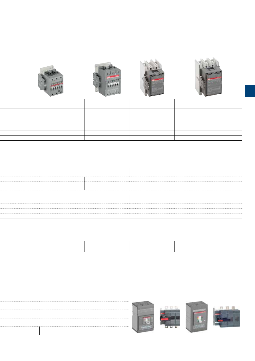
IEC
(1)
AC-3 Rated operational power
θ
≤ 55 °C, 400 V
kW
4
5.5
7.5
11
15
18.5
22
30
37
45
55
75
90
110
140
160
UL/CSA 3-phase motor rating
480 V
hp
5
7.5
10
20
25
30
40
60
60
60
75
100
125
150
200
250
AC Control supply
Type
A9
A12
A16
A26
A30
A40
A50
A63
A75
A95
A110
A145
A185
A210
A260
A300
IEC
AC-3 Rated operational current
θ
≤ 55 °C , 400 V
A
9
12
17
26
32
37
50
65
75
96
110
145
185
210
260
305
AC-1 Rated operational current
θ
≤ 40 °C, 690 V
A
25
27
30
45
55
60
100
115
125
145
160
250
275
350
400
500
UL/CSA General use rating
600 V
A
21
25
30
40
50
60
80
90
105
125
150
230
250
300
350
400
NEMA
NEMA Size
00
0
—
1
1P
—
2
—
3
—
—
4
—
—
5
—
(1) 1000 V IEC ratings available for A50 ... A300 contactors.
Main accessories
Auxiliary contact blocks
Front mounting
CA5-10
(1 x N.O.)
CA5-01
(1 x N.C.)
Side mounting
CAL5-11
(1 x N.O. + 1 x N.C.)
CAL18-11
(1 x N.O. + 1 x N.C.)
Timers
Electronic
TEF5-ON
TEF5-OFF
TE5S
(for star-delta starters - direct timing - separate mounting)
Interlocking units
Mechanical
VM5-1
VM300H
VM300V
Mechanical / Electrical
VE5-1
VE5-2
Surge suppressors
Varistor (AC/DC)
RV5
(24...440 V)
RC Type (AC)
RC5-1
(24...440 V)
RC5-2
(24...440 V)
RC5-3
(250...440 V)
Overload relays
Thermal relays
Class 10A
(Class 10A or 20 for TA80DU)
(Class 30 for TA450SU)
TA25DU-M
(0.10…32 A)
TA75DU-M
(18…80 A)
TA80DU
(29...80 A)
TA200DU
(66...200 A)
TA450DU
(130...310 A)
TA42DU-M
(18…42 A)
TA110DU
(66...110 A)
TA450SU
(40...310 A)
Manual motor starters
Short-circuit protection devices
Thermal / magnetic protection
Class 10
MS116
(0.10...32 A)
lcs up to 50 kA for class 10 A
MS450
(28...50 A)
lcs up to 50 kA
Tmax
Circuit breaker and accessories
MS132
(0.10...32 A)
lcs up to 100 kA
MS495
(45…100 A)
Ics up to 50 kA
MS497
(22…100 A)
Ics up to 100 kA
Magnetic only types
MO132
(0.16...32 A)
Ics up to 100 kA
MO496
(32…100 A)
Ics up to 100 kA
MO450
(40…50 A)
Ics up to 50 kA
MO495
(63…100 A)
Ics up to 50 kA
1S
B
C
101
87
5
S
0
2
01
.in
d
d
ABB
|
1
/3
1
1S
B
C
101
87
5
S
0
2
01
ABB
|
3
/3
3
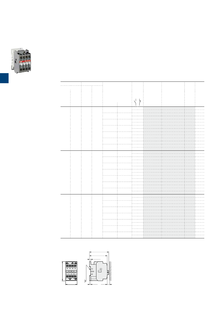
1S
B
C
101
8
5
5
S
0
2
01
3
/4 |
ABB
1SBC573122F0301
A9-30-10
A9 ... A16 3-pole contactors
4 to 7.5 kW
AC operated
Main dimensions
mm,
inches
44
1.73"
74
2.91"
68
2.68"
74
2.91"
5.5
0.22"
4
0.16"
10
0.39"
35 mm
EN/IEC 60715
A9, A12, A16
Description
A9 … A16 contactors are mainly used for controlling 3-phase motors and power circuits up to 690 V AC or
220 V DC.
These contactors are of the block type design with:
– 3 main poles and 1 built-in auxiliary contact
– control circuit: AC operated
– add-on auxiliary contact blocks for front or side mounting and a wide range of accessories.
Ordering details
IEC
UL/CSA
Rated control circuit
voltage
Uc
(1)
Auxiliary
contacts
fitted
Type
Order code
Weight
Pkg
(1 pce)
Rated operational
3-phase
motor
rating
480 V
General
use
rating
600 V AC
power
400 V
AC-3
current
θ
≤ 40 °C
AC-1
kW
A
hp
A
V 50 Hz
V 60 Hz
kg
4
25
5
21
24
24
1 0
A9-30-10
0.340
0 1
A9-30-01
0.340
48
48
1 0
A9-30-10
0.340
0 1
A9-30-01
0.340
110
110…120
1 0
A9-30-10
0.340
0 1
A9-30-01
0.340
220…230
230…240
1 0
A9-30-10
0.340
0 1
A9-30-01
0.340
230…240
240…260
1 0
A9-30-10
0.340
0 1
A9-30-01
0.340
380…400
400…415
1 0
A9-30-10
0.340
0 1
A9-30-01
0.340
400…415
415…440
1 0
A9-30-10
0.340
0 1
A9-30-01
0.340
5.5
27
7.5
25
24
24
1 0
A12-30-10
0.340
0 1
A12-30-01
0.340
48
48
1 0
A12-30-10
0.340
0 1
A12-30-01
0.340
110
110…120
1 0
A12-30-10
0.340
0 1
A12-30-01
0.340
220…230
230…240
1 0
A12-30-10
0.340
0 1
A12-30-01
0.340
230…240
240…260
1 0
A12-30-10
0.340
0 1
A12-30-01
0.340
380…400
400…415
1 0
A12-30-10
0.340
0 1
A12-30-01
0.340
400…415
415…440
1 0
A12-30-10
0.340
0 1
A12-30-01
0.340
7.5
30
10
30
24
24
1 0
A16-30-10
0.340
0 1
A16-30-01
0.340
48
48
1 0
A16-30-10
0.340
0 1
A16-30-01
0.340
110
110…120
1 0
A16-30-10
0.340
0 1
A16-30-01
0.340
220…230
230…240
1 0
A16-30-10
0.340
0 1
A16-30-01
0.340
230…240
240…260
1 0
A16-30-10
0.340
0 1
A16-30-01
0.340
380…400
400…415
1 0
A16-30-10
0.340
0 1
A16-30-01
0.340
400…415
415…440
1 0
A16-30-10
0.340
0 1
A16-30-01
0.340
(1) Other control voltages see voltage code table.
3
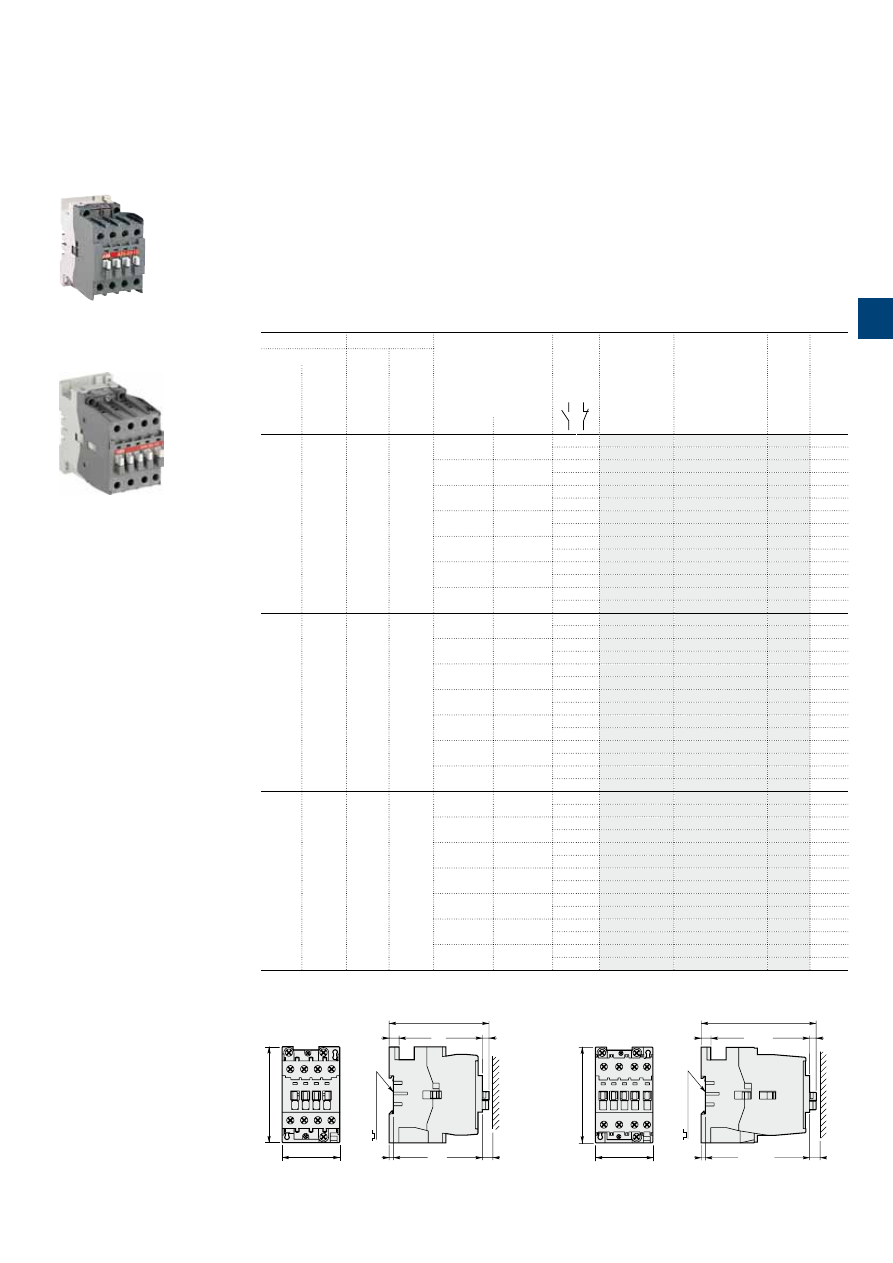
1S
B
C
101
8
5
6
S
0
2
01
ABB
|
3
/5
1SBC573092F0301
A26-30-10
1SBC101355F0014
A40-30-10
A26 ... A40 3-pole contactors
11 to 18.5 kW
AC operated
Main dimensions
mm,
inches
54
2.13"
90
3.54"
4
0.16"
10
0.39"
6.3
0.25"
93.6
3.69"
9
0.35"
35 mm
EN/IEC 60715
A26
54
2.13"
90
3.54"
108.3
4.26"
9
0.35"
6.3
0.25"
4
0.16"
10
0.39"
35 mm
EN/IEC 60715
A30, A40
Description
A26 ... A40 contactors are mainly used for controlling 3-phase motors and power circuits up to 690 V AC or
220 V DC.
These contactors are of the block type design with:
– 3 main poles and 1 built-in auxiliary contact
– control circuit: AC operated
– add-on auxiliary contact blocks for front or side mounting and a wide range of accessories.
Ordering details
IEC
UL/CSA
Rated control circuit
voltage
Uc
(1)
Auxiliary
contacts
fitted
Type
Order code
Weight
Pkg
(1 pce)
Rated operational
3-phase
motor
rating
480 V
General
use
rating
600 V AC
power
400 V
AC-3
current
θ
≤ 40 °C
AC-1
kW
A
hp
A
V 50 Hz
V 60 Hz
kg
11
45
20
40
24
24
1 0
A26-30-10
0.600
0 1
A26-30-01
0.600
48
48
1 0
A26-30-10
0.600
0 1
A26-30-01
0.600
110
110…120
1 0
A26-30-10
0.600
0 1
A26-30-01
0.600
220…230
230…240
1 0
A26-30-10
0.600
0 1
A26-30-01
0.600
230…240
240…260
1 0
A26-30-10
0.600
0 1
A26-30-01
0.600
380…400
400…415
1 0
A26-30-10
0.600
0 1
A26-30-01
0.600
400…415
415…440
1 0
A26-30-10
0.600
0 1
A26-30-01
0.600
15
55
25
50
24
24
1 0
A30-30-10
0.710
0 1
A30-30-01
0.710
48
48
1 0
A30-30-10
0.710
0 1
A30-30-01
0.710
110
110…120
1 0
A30-30-10
0.710
0 1
A30-30-01
0.710
220…230
230…240
1 0
A30-30-10
0.710
0 1
A30-30-01
0.710
230…240
240…260
1 0
A30-30-10
0.710
0 1
A30-30-01
0.710
380…400
400…415
1 0
A30-30-10
0.710
0 1
A30-30-01
0.710
400…415
415…440
1 0
A30-30-10
0.710
0 1
A30-30-01
0.710
18.5
60
30
60
24
24
1 0
A40-30-10
0.710
0 1
A40-30-01
0.710
48
48
1 0
A40-30-10
0.710
0 1
A40-30-01
0.710
110
110…120
1 0
A40-30-10
0.710
0 1
A40-30-01
0.710
220…230
230…240
1 0
A40-30-10
0.710
0 1
A40-30-01
0.710
230…240
240…260
1 0
A40-30-10
0.710
0 1
A40-30-01
0.710
380…400
400…415
1 0
A40-30-10
0.710
0 1
A40-30-01
0.710
400…415
415…440
1 0
A40-30-10
0.710
0 1
A40-30-01
0.710
(1) Other control voltages see voltage code table.
3
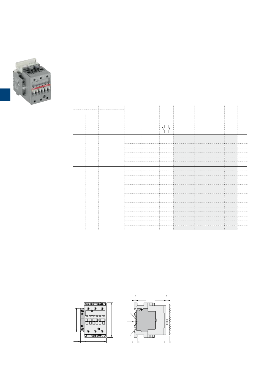
1S
B
C
101
3
6
4
S
0
2
01
3
/6 |
ABB
Main dimensions
mm,
inches
70
2.76"
12
0.47"
110
4.33"
74
2.91"
A50, A63, A75
6.5
0.26"
6
0.24"
10
0.39"
4
0.16"
10
0.39"
75 mm
EN/IEC 60715
35 mm x15
EN/IEC 60715
108
4.25"
A50 ... A75 3-pole contactors
22 to 37 kW
AC operated
Description
A50 ... A75 contactors are mainly used for controlling 3-phase motors and power circuits up to 690 V AC /
1000 V AC or 220 V DC.
These contactors are of the block type design with:
– 3 main poles
– control circuit: AC operated
– add-on auxiliary contact blocks for front or side mounting and a wide range of accessories.
Ordering details
IEC
UL/CSA
Rated control circuit
voltage
Uc
(1)
Auxiliary
contacts
fitted
Type
Order code
Weight
Pkg
(1 pce)
Rated operational
3-phase
motor
rating
480 V
General
use
rating
600 V AC
power
400 V
AC-3
current
θ
≤ 40 °C
AC-1
kW
A
hp
A
V 50 Hz
V 60 Hz
kg
22
100
40
80
24
24
1 1
A50-30-11
1.200
48
48
1 1
A50-30-11
1.200
110
110…220
1 1
A50-30-11
1.200
220…230
230…240
1 1
A50-30-11
1.200
230…240
240…260
1 1
A50-30-11
1.200
380…400
400…415
1 1
A50-30-11
1.200
400…415
415…440
1 1
A50-30-11
1.200
30
115
60
90
24
24
1 1
A63-30-11
1.200
48
48
1 1
A63-30-11
1.200
110
110…220
1 1
A63-30-11
1.200
220…230
230…240
1 1
A63-30-11
1.200
230…240
240…260
1 1
A63-30-11
1.200
380…400
400…415
1 1
A63-30-11
1.200
400…415
415…440
1 1
A63-30-11
1.200
37
125
60
105
24
24
1 1
A75-30-11
1.200
48
48
1 1
A75-30-11
1.200
110
110…220
1 1
A75-30-11
1.200
220…230
230…240
1 1
A75-30-11
1.200
230…240
240…260
1 1
A75-30-11
1.200
380…400
400…415
1 1
A75-30-11
1.200
400…415
415…440
1 1
A75-30-11
1.200
(1) Other control voltages see voltage code table.
1SBC101360F0010
A50-30-11
3
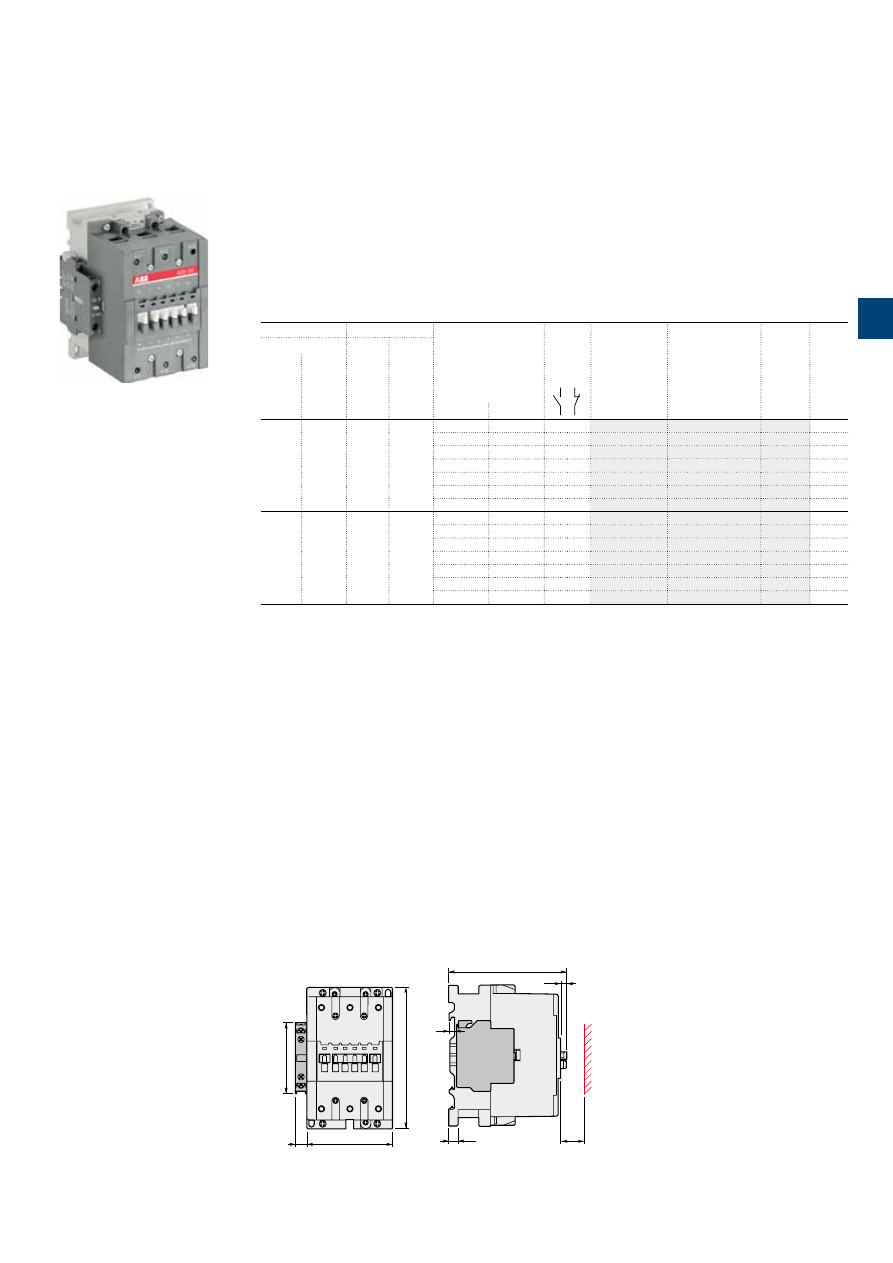
1SFC101146C0201
A95 … A110 3-pole contactors
45 to 55 kW
AC operated
Description
A95 ... A110 contactors are mainly used for controlling 3-phase motors and power circuits up to
690 / 1000 V AC or 220 V DC.
These contactors are of the block type design with:
- 3 main poles
- control circuit: AC operated
- add-on auxiliary contact blocks for front or side mounting and a wide range of accessories.
Ordering details
IEC
UL / CSA
Rated control circuit
voltage
Uc
(1)
Auxiliary
contacts
fitted
Type
Order code
Weight
Pkg
(1 pce)
Rated operational
3-phase
motor
rating
General
use
rating
power
current
θ
≤ 40 °C
400 V
480 V
600 V AC
AC-3
AC-1
kW
A
hp
A
V 50 Hz
V 60 Hz
kg
45
145
60
125
24
24
1 1
A95-30-11
2.040
48
48
1 1
A95-30-11
2.040
110
110…120
1 1
A95-30-11
2.040
220…230
230…240
1 1
A95-30-11
2.040
230…240
240…260
1 1
A95-30-11
2.040
380…400
400…415
1 1
A95-30-11
2.040
400…415
415…440
1 1
A95-30-11
2.040
55
160
75
140
24
24
1 1
A110-30-11
2.040
48
48
1 1
A110-30-11
2.040
110
110…120
1 1
A110-30-11
2.040
220…230
230…240
1 1
A110-30-11
2.040
230…240
240…260
1 1
A110-30-11
2.040
380…400
400…415
1 1
A110-30-11
2.040
400…415
415…440
1 1
A110-30-11
2.040
(1) Other control voltages see voltage code table.
1SBC573242F0301
A95-30-11
Main dimensions
mm,
inches
12
0.47"
90
3.54"
148
5.83"
E0787D
74
2.91"
123.5
4.86"
6
0.24"
E0788D1
20
10
0.39"
6.5
0.26"
0.79"
A95, A110
ABB
|
3
/7
3
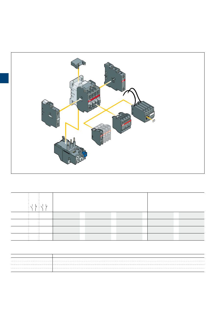
1S
B
C
10
18
71
S
0
2
01
3
/8 |
ABB
A9 … A110 3-pole contactors
Main accessories
Main accessory fitting details
Many configurations of accessories are possible depending on whether these are front-mounted or side-mounted.
Contactor
types
Main
poles
Built-in
auxiliary
contacts
Front-mounted accessories
Side-mounted accessories
Auxiliary contact blocks
Electronic timer
Auxiliary contact blocks
Interlock unit
1-pole CA5
4-pole CA5
TEF5
2-pole CAL
VM5 or VE5
A9 ... A26
3 0
1 0
1 to 4 x CA5
or
1 x CA5 (4-pole)
or
1 x TEF5
+
1 to 2 x CAL5-11
or
1 x VM5-1 or VE5-1
3 0
0 1 (1)
+1 x CAL5-11
A30, A40
3 0
1 0
1 to 5 x CA5
or
1 x CA5 (4-pole)
or
1 x TEF5
+
1 to 2 x CAL5-11
or
1 x VM5-1 or VE5-1
3 0
0 1 (1)
+ 1 x 1-pole CA5
+ 1 x CA5 (1-pole)
+1 x CAL5-11
A50 ... A75
3 0
1 1
1 to 6 x CA5
or
1 x CA5 (4-pole)
or
1 x TEF5
+
1 x CAL5-11
or
1 x VE5-2
+ 2 x 1-pole CA5
+ 2 x CA5 (1-pole)
A95, A110
3 0
1 1
1 to 6 x CA5
or
1 x CA5 (4-pole)
–
+
1 x CAL18-11
or
1 x VE5-2
+ 2 x 1-pole CA5
(1) 2 N.C. CA5 auxiliary contacts maximum in mounting position 5.
Overload relays fitting details
(2)
Contactor types
Thermal overload relays
A9 ... A26
TA25DU-M (0.1...0.32 A)
A30, A40
TA25DU-M (0.1...0.32 A) or TA42DU-M (18...42 A)
A50 … A75
TA75DU-M (18...80 A)
A95, A110
TA80DU (29...80 A) or TA110DU (65...110 A)
The addition of a thermal overload relay on the contactor does not prevent fitting of many other accessories as shown above.
(2) Direct mounting - No kit required.
Contactor and main accessories
(other accessories available)
RV5, RC5
Surge suppressor
VE5
Interlock unit
CAL
2-pole auxiliary
contact block
CA5
1-pole auxiliary
contact block
CA5
4-pole auxiliary
contact block
TA
Thermal overload relay
A
contactor
A1
A2
TEF5
Electronic timer
BX4-CA
Protective cover
3
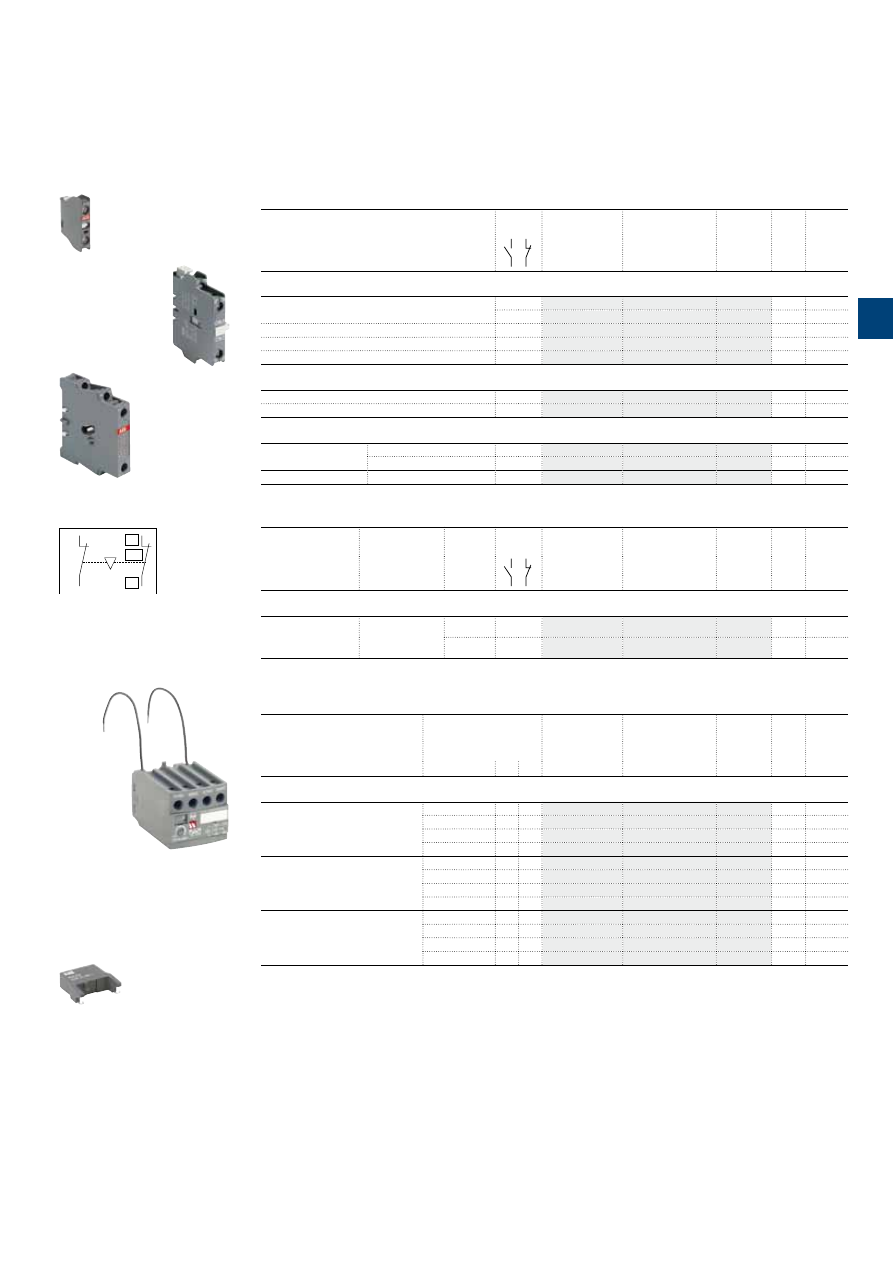
1S
B
C
101
872
S
0
2
01
ABB
|
3
/9
A9 … A110 3-pole contactors
Main accessories
Ordering details
(1)
For contactors
Auxiliary
contacts
Type
Order code
Pkg
qty
Weight
(1 pce)
kg
Front-mounted instantaneous auxiliary contact blocks
A9 ... A110
1 –
CA5-10
10
0.014
– 1
CA5-01
10
0.014
A9-30-10 ... A40-30-10
2 2
CA5-22M
2
0.060
A9-30-01 ... A40-30-01
2 2
CA5-22U
2
0.060
A50 ... A110
2 2
CA5-22E
2
0.060
Side-mounted instantaneous auxiliary contact block
A9 … A75
1 1
CAL5-11
2
0.050
A95, A110
1 1
CAL18-11
2
0.050
Interlock units
A9 ... A40
Mechanical
– –
VM5-1
1
0.066
Mechanical and electrical
– 2
VE5-1
1
0.076
A50 ... A110
Mechanical and electrical
– 2
VE5-2
1
0.146
For contactors
Time delay
range
selected by
switch
Delay
type
Auxiliary
contacts
Type
Order code
Pkg
qty
Weight
(1 pce)
kg
Electronic timers
A9 ... A75
0.1...1 s
1...10 s
10...100 s
ON-delay
1 1
TEF5-ON
1
0.065
OFF-delay
1 1
TEF5-OFF
1
0.065
Note: Rated control circuit voltage Uc 24...240 V 50/60 Hz or DC.
For contactors
Rated control circuit
voltage
Uc
Type
Order code
Pkg
qty
Weight
(1 pce)
V
AC DC
kg
Surge suppressors
A9 ... A110
24...50
●
●
RV5/50
2
0.015
50...133
●
●
RV5/133
2
0.015
110...250
●
●
RV5/250
2
0.015
250...440
●
●
RV5/440
2
0.015
A9 ... A40
24...50
●
–
RC5-1/50
2
0.012
50...133
●
–
RC5-1/133
2
0.012
110...250
●
–
RC5-1/250
2
0.012
250...440
●
–
RC5-1/440
2
0.012
A50 … A110
24...50
●
–
RC5-2/50
2
0.015
50...133
●
–
RC5-2/133
2
0.015
110...250
●
–
RC5-2/250
2
0.015
250...440
●
–
RC5-2/440
2
0.015
(1) See "Main accessory fitting details" table.
1SBC574001F0301
RV5/50
CA5-10
1SBC580992F0301
CAL5-11
1SBC573752F0301
01
02
NC
01
02
NC
VE5-1, VE5-2
Terminal marking and positioning
VE5-1
1SBC572822F0301
TEF5-OFF
1SBC101396F0014
3
N1
3
/10 |
ABB
3
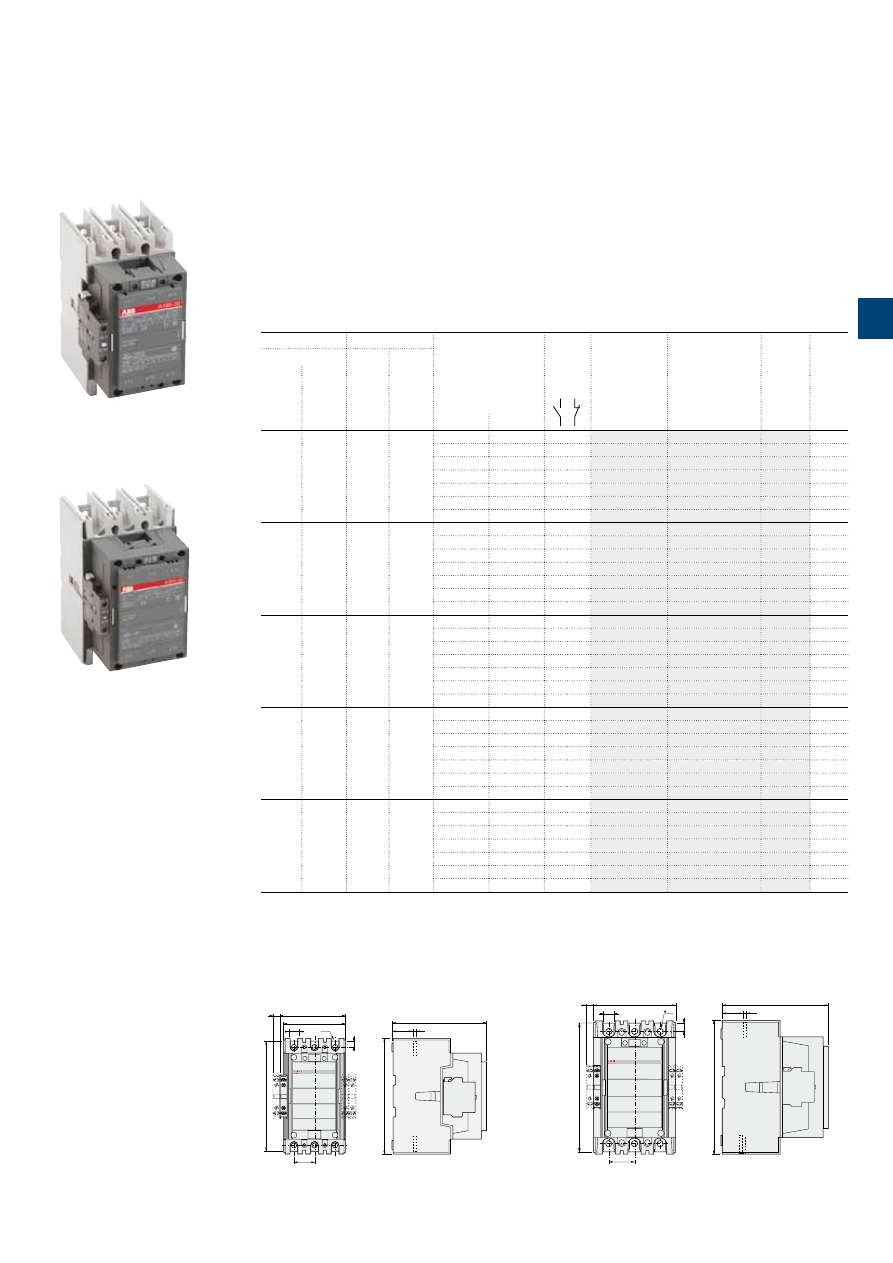
Main dimensions
mm,
inches
12
0.47"
17.5
0.69"
105
4.13"
111.5
4.39"
ø 8.5
0.33"
35
1.38"
10
0.39"
187
7.36"
E2001D
E2002D
160
6.3"
35.5
1.4"
196
7.72"
5
0.2"
E2016D
43.75
1.72"
10.2
0.4"
14
0.55"
140
5.51"
12
0.47"
19.5
0.77"
225
8.86"
E2017D
180.5
7.11"
5
0.2"
35.5
1.4"
227
8.94"
A145, A185
A210, A260, A300
A145 ... A300 3-pole contactors
75 to 160 kW
AC operated
Description
A145 ... A300 contactors are mainly used for controlling 3-phase motors and power circuits up to
690 / 1000 V AC (2) or 220 V DC.
These contactors are of the block type design with:
– 3 main poles
– control circuit: AC operated
– add-on auxiliary contact blocks for side mounting and a wide range of accessories.
Ordering details
IEC
UL / CSA
Rated control circuit
voltage
Uc
(1)
Auxiliary
contacts
fitted
Type
Order code
Weight
Pkg
(1 pce)
Rated operational
3-phase
motor
rating
General
use
rating
power
current
θ
≤ 40 °C
400 V
690 V
480 V
600 V AC
AC-3
AC-1
kW
A
hp
A
V 50 Hz
V 60 Hz
kg
75
250
100
230
24
24
1 1
A145-30-11
3.500
48
48
1 1
A145-30-11
3.500
110
110…120
1 1
A145-30-11
3.500
220…230
230…240
1 1
A145-30-11
3.500
230…240
240…260
1 1
A145-30-11
3.500
380…400
400…415
1 1
A145-30-11
3.500
400…415
415…440
1 1
A145-30-11
3.500
90
275
125
250
24
24
1 1
A185-30-11
3.500
48
48
1 1
A185-30-11
3.500
110
110…120
1 1
A185-30-11
3.500
220…230
230…240
1 1
A185-30-11
3.500
230…240
240…260
1 1
A185-30-11
3.500
380…400
400…415
1 1
A185-30-11
3.500
400…415
415…440
1 1
A185-30-11
3.500
110
350
150
300
24
24
1 1
A210-30-11
6.100
48
48
1 1
A210-30-11
6.100
110
110…120
1 1
A210-30-11
6.100
220…230
230…240
1 1
A210-30-11
6.100
230…240
240…260
1 1
A210-30-11
6.100
380…400
400…415
1 1
A210-30-11
6.100
400…415
415…440
1 1
A210-30-11
6.100
140
400
200
350
24
24
1 1
A260-30-11
6.100
48
48
1 1
A260-30-11
6.100
110
110…120
1 1
A260-30-11
6.100
220…230
230…240
1 1
A260-30-11
6.100
230…240
240…260
1 1
A260-30-11
6.100
380…400
400…415
1 1
A260-30-11
6.100
400…415
415…440
1 1
A260-30-11
6.100
160
500
250
400
24
24
1 1
A300-30-11
6.100
48
48
1 1
A300-30-11
6.100
110
110…120
1 1
A300-30-11
6.100
220…230
230…240
1 1
A300-30-11
6.100
230…240
240…260
1 1
A300-30-11
6.100
380…400
400…415
1 1
A300-30-11
6.100
400…415
415…440
1 1
A300-30-11
6.100
(1) Other control voltages see voltage code table.
(2) 690 V AC for A210 ... A300, 1000 V AC for A145, A185.
1SFC101029F0201
A185-30-11
1SFC101030F0201
A300-30-11
ABB
|
3
/11
1S
FC
101
14
7C
0
2
01
3
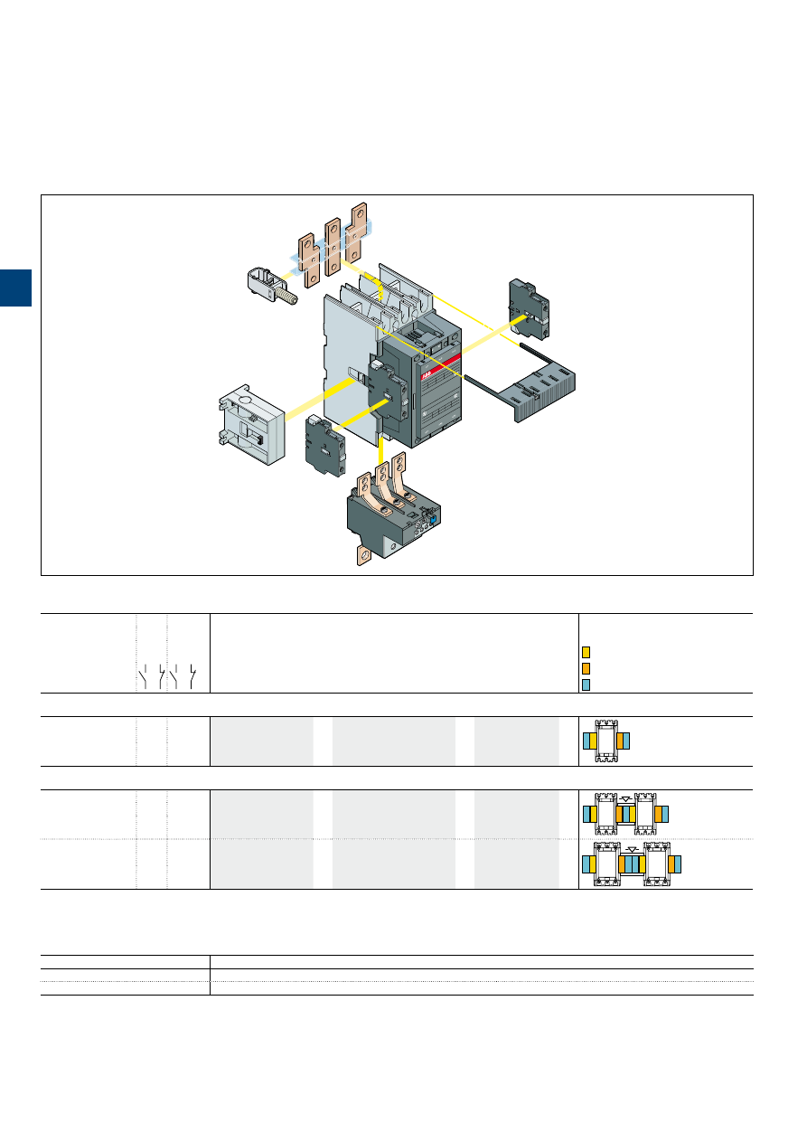
A145 ... A300 3-pole contactors
Main accessories
Main accessory fitting details
Contactor
types
Main
poles
Available
auxiliary
contacts
Side-mounted accessories
Add-on auxiliary contact blocks
Mechanical
interlock units
Mounting and positioning
Factory mounted auxiliary contacts
Add-on CAL18-11 auxiliary contacts
Add-on CAL18-11B auxiliary contacts
CAL18-11, CAL18-11B
Contactors + auxiliary contact blocks
A145 ... A300
3 0 1 1
1 x CAL18-11
+
2 x CAL18-11B
–
B
B
Contactors with mechanical interlocking + auxiliary contact blocks
A145 ... A185
3 0 1 1
2 x CAL18-11
(1)
+
3 x CAL18-11B
(1)
+
VM...H
(2)
B
B
B
A210 ... A300
3 0 1 1
2 x CAL18-11
(1)
+
4 x CAL18-11B
(1)
+
VM...H
(2)
B
B
B B
(1) Total number of auxiliary contact blocks for the two contactors.
(2) Interlock type, according to the contactor ratings (see "Accessories").
Main accessories
(other accessories available)
Overload relays fitting details
Contactor types
Thermal overload relays
A145, A185
TA200DU (66...200 A) (3)
A210, A300
TA450DU (130...310 A) (3) or TA450SU (40...310 A) (4)
The addition of a thermal or electronic overload relay on the contactor does not prevent fitting of many other accessories as shown in "Main accessory fitting details" table.
(3) Direct mounting - No kit required.
(4) Mounting kit required.
LW
Terminal
enlargement
CAL18-11
2-pole auxiliary
contact block
CAL18-11B
2-pole auxiliary
contact block
TA
Thermal overload relay
A
contactor
VM
Mechanical
interlock
LZ
Connector
terminal
LT
Terminal
shroud
3
/12 |
ABB
1S
FC
101
14
8
C
0
2
01
3
A145 ... A300 3-pole contactors
Main accessories
Ordering details
(1)
For contactors
Auxiliary
contacts
Type
Order code
Pkg
qty
Weight
(1 pce)
kg
Side-mounted instantaneous auxiliary contact blocks
A145 ... A300
1
1
CAL18-11
2
0.050
1
1
CAL18-11B
2
0.050
Mechanical interlock unit for two horizontal mounted contactors
A145 ... A300
VM300H
1
0.150
Terminal shrouds
A145 ... A185 with connectors
LT185-AC
2
0.050
A145 ... A185 with lugs
LT185-AL
2
0.220
A145 ... A185 with short. bar LY185
or between A145 and TA200DU
or between A185 and TA200DU
LT185-AY
1
0.050
A210 ... A300 with connectors
LT300-AC
2
0.070
A210 ... A300 with lugs
LT300-AL
2
0.280
A210 ... A300 with short bar LY300
LT300-AY
1
0.075
For contactors
Dimensions
Type
Order code
Pkg
Weight
hole Ø
mm
bar
mm
qty
(1 pce)
kg
Terminal enlargements
A145, A185
10.5
20 x 5
LW185
1
0.250
A210 ... A300
10.5
25 x 5
LW300
1
0.450
Terminal extension
A145, A185
8.5
20 x 5
LX185
1
0.250
A210 ... A300
10.5
20 x 5
LX300
1
0.350
Cables
For contactors
Cable cross section
Type
Order code
Pkg
qty
Weight
(1 pce)
mm²
kg
Connector terminals
Single Cu
A145, A185
6...185
–
3
0.200
A210 ... A300
16...240
–
3
0.400
Single Al & Cu
A145, A185
35...95
–
3
0.100
A145, A185
25...150
–
3
0.100
A210 ... A300
120...240
–
3
0.200
Double Cu
A145, A185
2 x (50...120)
LZ185-2C/120
3
0.300
Double Al & Cu
A210 ... A300
2 x (95...120)
–
3
0.400
(1) For each contactor type, refer to "Main accessory fitting details" table.
For contactors
Rated control circuit
voltage
Uc
Type
Order code
Pkg
qty
Weight
(1 pce)
V AC
kg
A145 ... A300
250...440
RC5-3/440
2
0.028
1SFT98099-019C3
LT...AC
1SFC101033F0201
CAL18-11
1SBC580411F0301
VM300H
1SFT9099-125
LT...AL
1SFT98000-014
LT...AY
1SFT98000-011C3
LW
1SFT98000-012C3
LX
1SFT98099-011C1
LZ
1SFT98099-095C2
LZ
1SBC580542F0302
LZ
ABB
|
3
/13
1S
FC
101
14
9
C
0
2
01
3
1S
B
C
101
8
5
9
S
0
2
01
3
/14 |
ABB
A9 ... A30 3-pole contactors
Technical data
Main pole - Utilization characteristics according to IEC
Contactor types
AC operated
A9
A12
A16
A26
A30
Standards
IEC 60947-1 / 60947-4-1 and EN 60947-1 / 60947-4-1
Rated operational voltage Ue max.
690 V
Rated frequency (without derating)
50 / 60 Hz
Conventional free-air thermal current Ith
acc. to IEC 60947-4-1, open contactors,
θ
≤ 40 °C
26 A
28 A
30 A
45 A
65 A
With conductor cross-sectional area
4 mm²
4 mm²
4 mm²
6 mm²
16 mm²
AC-1 Utilization category
For air temperature close to contactor
Ie / Rated operational current AC-1
θ
≤ 40 °C
25 A
27 A
30 A
45 A
55 A
Ue max. ≤ 690 V, 50/60 Hz
θ
≤ 55 °C
22 A
25 A
27 A
40 A
55 A
θ
≤ 70 °C
18 A
20 A
23 A
32 A
39 A
With conductor cross-sectional area
2.5 mm²
4 mm²
4 mm²
6 mm²
10 mm²
AC-3 Utilization category
For air temperature close to contactor
θ
≤ 55 °C
Ie / Max. rated operational current AC-3
(1)
M
3
3-phase motors
220-230-240 V
9 A
12 A
17 A
26 A
33 A
380-400 V
9 A
12 A
17 A
26 A
32 A
415 V
9 A
12 A
17 A
26 A
32 A
440 V
9 A
12 A
16 A
26 A
32 A
500 V
9 A
12 A
14 A
22 A
28 A
690 V
7 A
9 A
10 A
17 A
21 A
Rated operational power AC-3
(1)
M
3
1500 r.p.m. 50 Hz
1800 r.p.m. 60 Hz
3-phase motors
220-230-240 V
2.2 kW
3 kW
4 kW
6.5 kW
9 kW
380-400 V
4 kW
5.5 kW
7.5 kW
11 kW
15 kW
415 V
4 kW
5.5 kW
9 kW
11 kW
15 kW
440 V
4 kW
5.5 kW
9 kW
15 kW
18.5 kW
500 V
5.5 kW
7.5 kW
9 kW
15 kW
18.5 kW
690 V
5.5 kW
7.5 kW
9 kW
15 kW
18.5 kW
Rated making capacity AC-3
10 x Ie AC-3 acc. to IEC 60947-4-1
Rated breaking capacity AC-3
8 x Ie AC-3 acc. to IEC 60947-4-1
AC-8a Utilization category
(without thermal overload relay - Ue 400 V 50/60 Hz -
θ
≤ 40 °C)
Ie / Rated operational current AC-8a
12 A
16 A
22 A
30 A
40 A
Rated operational power AC-8a
5.5 kW
7.5 kW
11 kW
15 kW
20 kW
Short-circuit protection device for contactors
without thermal overload relay - Motor protection excluded (2)
Ue ≤ 500 V AC - gG type fuse
25 A
32 A
32 A
50 A
63 A
Rated short-time withstand current Icw
1 s
250 A
280 A
300 A
400 A
600 A
at 40 °C ambient temperature,
in free air from a cold state
10 s
100 A
120 A
140 A
210 A
400 A
30 s
60 A
70 A
80 A
110 A
225 A
1 min
50 A
55 A
60 A
90 A
150 A
15 min
26 A
28 A
30 A
45 A
65 A
Maximum breaking capacity
cos
φ
= 0.45
at 440 V
250 A
420 A
820 A
at 690 V
90 A
170 A
340 A
Power dissipation per pole
Ie / AC-1
0.8 W
1 W
1.2 W
1.8 W
2.5 W
Ie / AC-3
0.1 W
0.2 W
0.35 W
0.6 W
0.9 W
Max. electrical switching frequency
AC-1
600 cycle/h
AC-3
1200 cycle/h
AC-2, AC-4
300 cycle/h
(1) For the corresponding kW/A or hp/A values of 1500 r.p.m, 50 Hz or 1800 r.p.m, 60 Hz, 3-phase motors, see "Motor rated operational powers and currents".
(2) For the protection of motor starters against short circuits, see "Coordination with short-circuit protection devices".
3
1S
B
C
101
87
6
S
0
2
01
ABB
|
3
/15
A40 ... A110 3-pole contactors
Technical data
Main pole - Utilization characteristics according to IEC
Contactor types
AC operated
A40
A50
A63
A75
A95
A110
Standards
IEC 60947-1 / 60947-4-1 and EN 60947-1 / 60947-4-1
Rated operational voltage Ue max.
690 V
1000 V
Rated frequency (without derating)
50/60 Hz
Conventional free-air thermal current Ith
acc. to IEC 60947-4-1, open contactors,
θ
≤ 40 °C
65 A
100 A
125 A
125 A
145 A
160 A
With conductor cross-sectional area
16 mm²
35 mm²
50 mm²
50 mm²
50 mm²
70 mm²
AC-1 Utilization category
For air temperature close to contactor
Ie / Rated operational current AC-1
θ
≤ 40 °C
60 A
100 A
115 A
125 A
145 A
160 A
Ue max. ≤ 690 V, 50/60 Hz
θ
≤ 55 °C
60 A
85 A
95 A
105 A
135 A
145 A
θ
≤ 70 °C
42 A
70 A
80 A
85 A
115 A
130 A
With conductor cross-sectional area
16 mm²
35 mm²
50 mm²
50 mm²
50 mm²
70 mm²
AC-3 Utilization category
For air temperature close to contactor
θ
≤ 55 °C
Ie / Max. rated operational current AC-3
(1)
M
3
3-phase motors
220-230-240 V
40 A
53 A
65 A
75 A
96 A
110 A
380-400 V
37 A
50 A
65 A
75 A
96 A
110 A
415 V
37 A
50 A
65 A
75 A
96 A
110 A
440 V
37 A
45 A
65 A
70 A
93 A
100 A
500 V
33 A
45 A
55 A
65 A
80 A
100 A
690 V
25 A
35 A
43 A
46 A
65 A
82 A
1000 V
–
23 A
25 A
28 A
30 A
30 A
Rated operational power AC-3
(1)
M
3
1500 r.p.m. 50 Hz
1800 r.p.m. 60 Hz
3-phase motors
220-230-240 V
11 kW
15 kW
18.5 kW
22 kW
25 kW
30 kW
380-400 V
18.5 kW
22 kW
30 kW
37 kW
45 kW
55 kW
415 V
18.5 kW
25 kW
37 kW
40 kW
55 kW
59 kW
440 V
22 kW
25 kW
37 kW
40 kW
55 kW
59 kW
500 V
22 kW
30 kW
37 kW
45 kW
55 kW
59 kW
690 V
22 kW
30 kW
37 kW
40 kW
55 kW
75 kW
1000 V
–
30 kW
33 kW
37 kW
40 kW
40 kW
Rated making capacity AC-3
10 x Ie AC-3 acc. to IEC 60947-4-1
Rated breaking capacity AC-3
8 x Ie AC-3 acc. to IEC 60947-4-1
AC-8a Utilization category
(without thermal overload relay - Ue 400 V 50/60 Hz -
θ
≤ 40 °C)
Ie / Rated operational current AC-8a
50 A
63 A
85 A
95 A
120 A
140 A
Rated operational power AC-8a
22 kW
30 kW
45 kW
45 kW
55 kW
75 kW
Short-circuit protection device for contactors
without thermal overload relay - Motor protection excluded (2)
Ue ≤ 500 V AC - gG type fuse
63 A
100 A
125 A
160 A
160 A
200 A
Rated short-time withstand current Icw
1 s
600 A
1000 A
1320 A
at 40 °C ambient temperature,
in free air from a cold state
10 s
400 A
650 A
800 A
30 s
225 A
370 A
500 A
1 min
150 A
250 A
350 A
15 min
65 A
110 A
135 A
135 A
160 A
175 A
Maximum breaking capacity
cos
φ
= 0.45
at 440 V
820 A
1300 A
1160 A
at 690 V
340 A
630 A
800 A
Power dissipation per pole
Ie / AC-1
3 W
5 W
6.5 W
7 W
6.5 W
7.5 W
Ie / AC-3
1.3 W
1.3 W
1.5 W
2 W
2.7 W
3.6 W
Max. electrical switching frequency
AC-1
600 cycles/h
300 cycles/h
AC-3
1200 cycles/h
600 cycles/h
300 cycles/h
AC-2, AC-4
300 cycles/h
150 cycles/h
(1) For the corresponding kW/A or hp/A values of 1500 r.p.m, 50 Hz or 1800 r.p.m, 60 Hz, 3-phase motors, see "Motor rated operational powers and currents".
(2) For the protection of motor starters against short circuits, see "Coordination with short-circuit protection devices".
3

A145 … A300 3-pole contactors
Technical data
Main pole - Utilization characteristics according to IEC
Contactor types
AC operated
A145
A185
A210
A260
A300
Standards
IEC 60947-1 / 60947-4-1 and EN 60947-1 / 60947-4-1
Rated operational voltage Ue max.
1000 V
690 V
Rated frequency (without derating)
50/60 Hz
Conventional free-air thermal current Ith
acc. to IEC 60947-4-1, open contactors,
θ
≤ 40 °C
250 A
275 A
350 A
400 A
500 A (4)
With conductor cross-sectional area (3)
120 mm²
150 mm²
185 mm²
240 mm²
300 mm² (4)
AC-1 Utilization category
For air temperature close to contactor
Ie / Rated operational current AC-1
θ
≤ 40 °C
250 A
275 A
350 A
400 A
500 A (4)
Ue max. ≤ 690 V, 50/60 Hz
θ
≤ 55 °C
230 A
250 A
300 A
350 A
400 A (4)
θ
≤ 70 °C
180 A
180 A
240 A
290 A
325 A (4)
Ie / Rated operational current AC-1
θ
≤ 40 °C
180 A
200 A
–
–
–
Ue max. ≤ 1000 V, 50/60 Hz
θ
≤ 55 °C
180 A
200 A
–
–
–
θ
≤ 70 °C
180 A
180 A
–
–
–
With conductor cross-sectional area
120 mm²
150 mm²
185 mm²
240 mm²
300 mm² (4)
AC-3 Utilization category
For air temperature close to contactor
θ
≤
55 °C
Ie / Max. rated operational current AC-3
(1)
M
3
3-phase motors
220-230-240 V
145 A
185 A
210 A
260 A
305 A
380-400 V
145 A
185 A
210 A
260 A
305 A
415 V
145 A
185 A
210 A
260 A
300 A
440 V
145 A
185 A
210 A
240 A
280 A
500 V
145 A
170 A
210 A
240 A
280 A
690 V
120 A
170 A
210 A
220 A
280 A
1000 V
80 A
95 A
–
–
–
Rated operational power AC-3
(1)
M
3
1500 r.p.m. 50 Hz
1800 r.p.m. 60 Hz
3-phase motors
220-230-240 V
45 kW
55 kW
59 kW
80 kW
90 kW
380-400 V
75 kW
90 kW
110 kW
140 kW
160 kW
415 V
75 kW
90 kW
110 kW
140 kW
160 kW
440 V
75 kW
90 kW
110 kW
140 kW
160 kW
500 V
90 kW
110 kW
132 kW
180 kW
200 kW
690 V
110 kW
132 kW
160 kW
200 kW
250 kW
1000 V
110 kW
132 kW
–
–
–
Rated making capacity AC-3
10 x Ie AC-3 acc. to IEC 60947-4-1
Rated breaking capacity AC-3
8 x Ie AC-3 acc. to IEC 60947-4-1
Short-circuit protection device for contactors
without thermal overload relay - Motor protection excluded (2)
Ue ≤ 500 V AC - gG type fuse
315 A
355 A
400 A
500 A
500 A
Rated short-time withstand current Icw
1 s
1800 A
2000 A
2500 A
3500 A
3500 A
at 40 °C ambient temperature,
in free air from a cold state
10 s
1200 A
1500 A
1700 A
2400 A
2400 A
30 s
800 A
1000 A
1200 A
1500 A
1500 A
1 min
600 A
800 A
1000 A
1100 A
1100 A
15 min
280 A
320 A
400 A
500 A
500 A
Maximum breaking capacity
cos
φ
= 0.45
at 440 V
1500 A
2000 A
2300 A
2600 A
3000 A
(cos
φ
= 0.35 for Ie > 100 A)
at 690 V
1200 A
1600 A
2000 A
2400 A
2500 A
Power dissipation per pole
Ie / AC-1
13 W
16 W
18 W
25 W
32 W
Ie / AC-3
5 W
8 W
9 W
14 W
18 W
Max. electrical switching frequency
AC-1
300 cycles/h
300 cycles/h
AC-3
300 cycles/h
300 cycles/h
AC-2, AC-4
150 cycles/h
150 cycles/h
(1) For the corresponding kW/A or hp/A values of 1500 r.p.m, 50 Hz or 1800 r.p.m, 60 Hz, 3-phase motors, see "Motor rated operational powers and currents".
(2) For the protection of motor starters against short circuits, see “Coordination with short-circuit protection devices”.
(3) Conductors with preparation.
(4) Use terminal extension / enlargement pieces (LX 300 / LW 300).
3
/16 |
ABB
1S
FC
10
115
0
C
0
2
01
3

1S
B
C
101
8
6
0
S
0
2
01
ABB
|
3
/17
A9 ... A30 3-pole contactors
Technical data
Main pole - Utilization characteristics according to UL / NEMA / CSA
Contactor types
AC operated
A9
A12
A16
A26
A30
Standards
UL 508, CSA C22.2 N°14
Max. operational voltage
600 V
NEMA size
00
0
–
1
1P
NEMA continuous amp rating
Thermal current
9 A
18 A
–
27 A
36 A
NEMA maximum horse power ratings
1-phase, 60 Hz
115 V AC
1/3 hp
1 hp
–
2 hp
3 hp
230 V AC
1 hp
2 hp
–
3 hp
5 hp
NEMA maximum horse power ratings
3-phase, 60 Hz
200 V AC
1-1/2 hp
3 hp
–
7-1/2 hp
–
230 V AC
1-1/2 hp
3 hp
–
7-1/2 hp
–
460 V AC
1-1/2 hp
5 hp
–
10 hp
–
575 V AC
2 hp
5 hp
–
10 hp
–
UL / CSA general use rating
600 V AC
21 A
25 A
30 A
40 A
50 A
With conductor cross-sectional area
AWG 10
AWG 8
UL / CSA maximum 1-phase motor rating
Full load current
120 V AC
9.8 A
13.8 A
16 A
28 A
34 A
240 V AC
12 A
12 A
17 A
24 A
40 A
Horse power rating
120 V AC
1/2 hp
3/4 hp
1 hp
2 hp
3 hp
240 V AC
2 hp
2 hp
3 hp
5 hp
7.5 hp
UL / CSA maximum 3-phase motor rating
Full load current (1)
200-208 V AC
7.8 A
11 A
17.5 A
25.3 A
32.2 A
220-240 V AC
6.8 A
9.6 A
15.2 A
28 A
28 A
440-480 V AC
7.6 A
11 A
14 A
27 A
34 A
550-600 V AC
9 A
11 A
17 A
27 A
32 A
Horse power rating (1)
200-208 V AC
2 hp
3 hp
5 hp
7.5 hp
10 hp
220-240 V AC
2 hp
3 hp
5 hp
10 hp
10 hp
440-480 V AC
5 hp
7.5 hp
10 hp
20 hp
25 hp
550-600 V AC
7.5 hp
10 hp
15 hp
25 hp
30 hp
Short-circuit protection device for contactors
without thermal overload relay - Motor protection excluded
Fuse rating
35 A
35 A
60 A
90 A
150 A
Fuse type, 600 V
FRS-R
Max. electrical switching frequency
For general use
600 cycles/h
For motor use
1200 cycles/h
(1) For the corresponding kW/A or hp/A values of 1500 r.p.m, 50 Hz or 1800 r.p.m, 60 Hz, 3-phase motors, see "Motor rated operational powers and currents".
General technical data
Contactor types
AC operated
A9
A12
A16
A26
A30
Rated insulation voltage Ui
acc. to IEC 60947-4-1
1000 V
acc. to UL / CSA
600 V
Rated impulse withstand voltage Uimp.
8 kV
Ambient air temperature close to contactor
Operation
Fitted with thermal overload relay
-25...+55 °C
Without thermal overload relay
-40...+70 °C
Storage
-60...+80 °C
Climatic withstand
acc. to IEC 60068-2-30 and 60068-2-11 - UTE C 63-100 specification II
Maximum operating altitude (without derating)
3000 m
Mechanical durability
Number of operating cycles
10 millions operating cycles
Max. switching frequency
3600 cycles/h
Shock withstand
acc. to IEC 60068-2-27 and EN 60068-2-27
Mounting position 1
B2
A
A B1
C2
C1
Shock direction
1/2 sinusoidal shock for 11 ms: no change in contact position, closed or open position
A
20 g
B1
10 g closed position / 5 g open position
B2
15 g
C1
20 g
C2
20 g
3
1S
B
C
101
87
7S
0
2
01
3
/18 |
ABB
A40 ... A110 3-pole contactors
Technical data
Main pole - Utilization characteristics according to UL / NEMA / CSA
Contactor types
AC operated
A40
A50
A63
A75
A95
A110
Standards
UL 508, CSA C22.2 N°14
Max. operational voltage
600 V
NEMA size
–
2
–
3
–
–
NEMA continuous amp rating
Thermal current
–
45 A
–
90 A
–
–
NEMA maximum horse power ratings
1-phase, 60 Hz
115 V AC
–
3 hp
–
–
–
–
230 V AC
–
7-1/2
–
–
–
–
NEMA maximum horse power ratings
3-phase, 60 Hz
200 V AC
–
10 hp
–
25 hp
–
–
230 V AC
–
15 hp
–
30 hp
–
–
460 V AC
–
25 hp
–
50 hp
–
–
575 V AC
–
25 hp
–
50 hp
–
–
UL / CSA general use rating
600 V AC
60 A
80 A
90 A
105 A
125 A
150 A
With conductor cross-sectional area
AWG 6
AWG 4
AWG 3
AWG 2
AWG 1
AWG 1/0
UL / CSA maximum 1-phase motor rating
Full load current
120 V AC
34 A
34 A
56 A
80 A
80 A
100 A
240 V AC
40 A
40 A
50 A
68 A
88 A
110 A
Horse power rating
120 V AC
3 hp
3 hp
5 hp
7.5 hp
7.5 hp
10 hp
240 V AC
7.5 hp
7.5 hp
10 hp
15 hp
20 hp
25 hp
UL / CSA maximum 3-phase motor rating
Full load current (1)
200-208 V AC
32.2 A
48.3 A
62.1 A
78.2 A
92 A
92 A
220-240 V AC
42 A
54 A
68 A
80 A
80 A
104 A
440-480 V AC
40 A
52 A
77 A
77 A
77 A
96 A
550-600 V AC
41 A
52 A
77 A
77 A
77 A
99 A
Horse power rating (1)
200-208 V AC
10 hp
15 hp
20 hp
25 hp
30 hp
30 hp
220-240 V AC
15 hp
20 hp
25 hp
30 hp
30 hp
40 hp
440-480 V AC
30 hp
40 hp
60 hp
60 hp
60 hp
75 hp
550-600 V AC
40 hp
50 hp
75 hp
75 hp
75 hp
100 hp
Short-circuit protection device for contactors
without thermal overload relay - Motor protection excluded
Fuse rating
150 A
175 A
200 A
200 A
200 A
200 A
Fuse type, 600 V
FRS-R
J
Max. electrical switching frequency
For general use
600 cycles/h
300 cycles/h
For motor use
1200 cycles/h
600 cycles/h
300 cycles/h
(1) For the corresponding kW/A or hp/A values of 1500 r.p.m, 50 Hz or 1800 r.p.m, 60 Hz, 3-phase motors, see "Motor rated operational powers and currents".
General technical data
Contactor types
AC operated
A40
A50
A63
A75
A95
A110
Rated insulation voltage Ui
acc. to IEC 60947-4-1
1000 V
acc. to UL / CSA
600 V
Rated impulse withstand voltage Uimp.
8 kV
Ambient air temperature close to contactor
Operation
Fitted with thermal overload relay
-25...+55 °C
Without thermal overload relay
-40…+70 °C
Storage
-60...+80 °C
-40...+70 °C
Climatic withstand
acc. to IEC 60068-2-30 and 60068-2-11
UTE C 63-100 specification II
acc. to IEC 60068-2-30
Maximum operating altitude (without derating)
3000 m
Mechanical durability
Number of operating cycles
10 millions operating cycles
Max. switching frequency
3600 cycles/h
Shock withstand
acc. to IEC 60068-2-27 and EN 60068-2-27
Mounting position 1
B2
A
A B1
C2
C1
Shock direction
1/2 sinusoidal shock for 11 ms: no change in contact position, closed or open position (2)
A
20 g
B1
10 g closed position / 5 g open position
B2
15 g
C1
20 g
C2
20 g
(2) These values are not valid for rail mounting with contactors A95 ... A110.
3
A145 … A300 3-pole contactors
Technical data
Main pole - Utilization characteristics according to UL / NEMA / CSA
Contactor types
AC operated
A145
A185
A210
A260
A300
Standards
UL 508, CSA C22.2 N°14
Maximum operational voltage
600 V
NEMA size
4
–
–
5
–
NEMA maximum horse power ratings
1-phase, 60 Hz
115 V AC
–
–
–
–
–
230 V AC
–
–
–
–
–
NEMA maximum horse power ratings
3-phase, 60 Hz
200 V AC
40 hp
75 hp
230 V AC
50 hp
100 hp
460 V AC
100 hp
200 hp
575 V AC
200 hp
200 hp
UL / CSA general use rating
600 V AC
230 A
250 A
300 A
350 A
400 A
UL / CSA maximum 1-phase motor rating
Full load current
240 V AC
–
–
–
–
–
Horse power rating
240 V AC
–
–
–
–
–
UL / CSA maximum 3-phase motor rating
Full load current (1)
200-208 V AC
119.6 A
149.5 A
166.8 A
220.8 A
285.2 A
220-240 V AC
130 A
145 A
192 A
248 A
248 A
440-480 V AC
124 A
156 A
180 A
240 A
302 A
550-600 V AC
125 A
144 A
192 A
242 A
289 A
Horse power rating (1)
200-208 V AC
40 hp
50 hp
60 hp
75 hp
100 hp
220-240 V AC
50 hp
60 hp
75 hp
100 hp
100 hp
440-480 V AC
100 hp
125 hp
150 hp
200 hp
250 hp
550-600 V AC
125 hp
150 hp
200 hp
250 hp
300 hp
Short-circuit protection device for contactors
without thermal overload relay - Motor protection excluded
Fuse rating
300 A
400 A
800 A
800 A
800 A
Fuse type, 600 V
J/K5
Maximum electrical switching frequency
For general use
300 cycles/h
For motor use
300 cycles/h
(1) For the corresponding kW/A or hp/A values of 1500 r.p.m, 50 Hz or 1800 r.p.m, 60 Hz, 3-phase motors, see “Motor rated operational powers and currents”.
General technical data
Contactor types
AC operated
A145
A185
A210
A260
A300
Rated insulation voltage Ui
acc. to IEC 60947-4-1
1000 V
acc. to UL / CSA
600 V
Rated impulse withstand voltage Uimp.
8 kV
Ambient air temperature close to contactor
Operation
Fitted with thermal overload relay
-25 to +55 °C
Storage
-40 to +70 °C
Climatic withstand
acc. to IEC 60068-2-30
Maximum operating altitude (without derating)
3000 m
Mechanical durability
Number of operating cycles
5 millions operating cycles
Max. switching frequency
3600 cycles/h
Shock withstand
acc. to IEC 60068-2-27 and EN 60068-2-27
Mounting position 1
B2
A
A
B1
C2
C1
ABB
Shock direction
1/2 sinusoidal shock for 30 ms: no change in contact position, closed or open position
A
5 g
B1
5 g
B2
5 g
C1
5 g
C2
5 g
ABB
|
3
/19
1S
FC
10
115
1C
0
2
01
3

1S
B
C
101
8
61
S
0
2
01
3
/20 |
ABB
A9 ... A30 3-pole contactors
Technical data
Magnet system characteristics
Contactor types
AC operated
A9
A12
A16
A26
A30
Coil operating limits
AC supply
at
θ
≤ 55 °C 0.85...1.1 x Uc
Please also refer to "Mounting characteristics and conditions for use"
acc. to IEC 60947-4-1
AC control voltage 50/60 Hz
Rated control circuit voltage Uc
at 50 Hz
24...690 V
at 60 Hz
24...690 V
Coil consumption
Average pull-in value
50 Hz
70 VA
120 VA
60 Hz
80 VA
140 VA
50/60 Hz
(1)
74 VA / 70 VA
125 VA / 120 VA
Average holding value
50 Hz
8 VA / 2 W
12 VA / 3 W
60 Hz
8 VA / 2 W
12 VA / 3 W
50/60 Hz
(1)
8 VA / 2 W
12 VA / 3 W
Drop-out voltage
approx. 40...65 % of Uc
Operating time
Between coil energization and:
N.O. contact closing
10...26 ms
8...21 ms
N.C. contact opening
7...21 ms
6...18 ms
Between coil de-energization and:
N.O. contact opening
4...11 ms
4...11 ms
N.C. contact closing
9...16 ms
7...14 ms
(1) 50/60 Hz coils: see "Coil voltage code table".
Mounting characteristics and conditions for use
Contactor types
AC operated
A9
A12
A16
A26
A30
Mounting positions
Pos. 5
Pos. 6
Pos. 3
Pos
. 2
Pos. 1
Pos. 1 ± 30°
+30°
-30°
Pos
. 4
Max. N.O. or N.C. built-in and add-on N.O. or N.C. auxiliary contacts:
see accessory fitting details for 3-pole contactor A9 ... A30
Control voltage / Ambient temperature
Mounting
positions
1, 1±30°, 2, 3, 4, 5
at
θ
≤ 55 °C
0.85…1.1 x Uc
at
θ
≤ 70 °C
Uc
6
at
θ
≤ 55 °C
0.95…1.1 x Uc
at
θ
≤ 70 °C
Unauthorized
Mounting distances
The contactors can be assembled side by side
Fixing
On rail according to IEC 60715, EN 60715
35 x 7.5 mm or 35 x 15 mm
By screws (not supplied)
2 x M4 screws placed diagonally
3
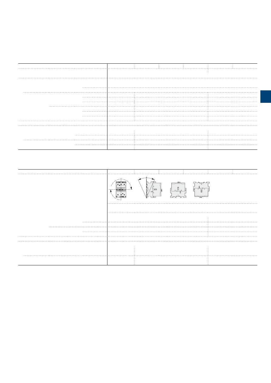
1S
B
C
101
87
8
S
0
2
01
ABB
|
3
/21
A40 ... A110 3-pole contactors
Technical data
Magnet system characteristics
Contactor types
AC operated
A40
A50
A63
A75
A95
A110
Coil operating limits
AC supply
At
θ
≤ 55 °C 0.85...1.1 x Uc
at
θ
≤ 70 °C 0.85...1.1 x Uc
acc. to IEC 60947-4-1
Please also refer to "Mounting characteristics and conditions for use"
AC control voltage 50/60 Hz
Rated control circuit voltage Uc
at 50 Hz
24…690 V
at 60 Hz
24…690 V
Coil consumption
Average pull-in value
50 Hz
120 VA
180 VA
350 VA
60 Hz
140 VA
210 VA
450 VA
50/60 Hz
(1)
125 VA / 120 VA 190 VA / 180 VA
410 VA / 365 VA
Average holding value
50 Hz
12 VA / 3 W
18 VA / 5.5 W
22 VA / 6.5 W
60 Hz
12 VA / 3 W
18 VA / 5.5 W
26 VA / 8 W
50/60 Hz
(1)
12 VA / 3 W
18 VA / 5.5 W
27 VA / 7.5 W
Drop-out voltage
Approx. 40...65 % of Uc
Operating time
Between coil energization and:
N.O. contact closing
8…21 ms
8…27 ms
10…25 ms
N.C. contact opening
6…18 ms
7…22 ms
7…22 ms
Between coil de-energization and:
N.O. contact opening
4…11 ms
4…11 ms
7…15 ms
N.C. contact closing
7…14 ms
7…14 ms
10…18 ms
(1) 50/60 Hz coils: see "Coil voltage code table".
Mounting characteristics and conditions for use
Contactor types
AC operated
A40
A50
A63
A75
A95
A110
Mounting positions
Pos. 5
Pos. 6
Pos. 3
Pos
. 2
Pos. 1
Pos. 1 ± 30°
+30°
-30°
Pos
. 4
Max. built-in and add-on N.O. or N.C. auxiliary contacts:
see accessory fitting details for 3-pole contactor A40 ... A110
Control voltage / Ambient temperature
Mounting
positions
1, 1±30°, 2, 3, 4, 5
at
θ
≤ 55 °C
0.85…1.1 x Uc
0.85…1.1 x Uc
at
θ
≤ 70 °C
Uc
0.85…1.1 x Uc
6
at
θ
≤ 55 °C
0.95...1.1 x Uc
Unauthorized
at
θ
≤ 70 °C
Unauthorized
Unauthorized
Mounting distances
The contactors can be assembled side by side
Fixing
On rail according to IEC 60715, EN 60715
35 x 7.5 mm or
35 x 15 mm
35 x 15 mm or
75 x 25 mm
–
By screws (not supplied)
2 x M4 screws
placed diagonally
2 x M6 screws
placed diagonally
2 x M6 screws
placed diagonally
3
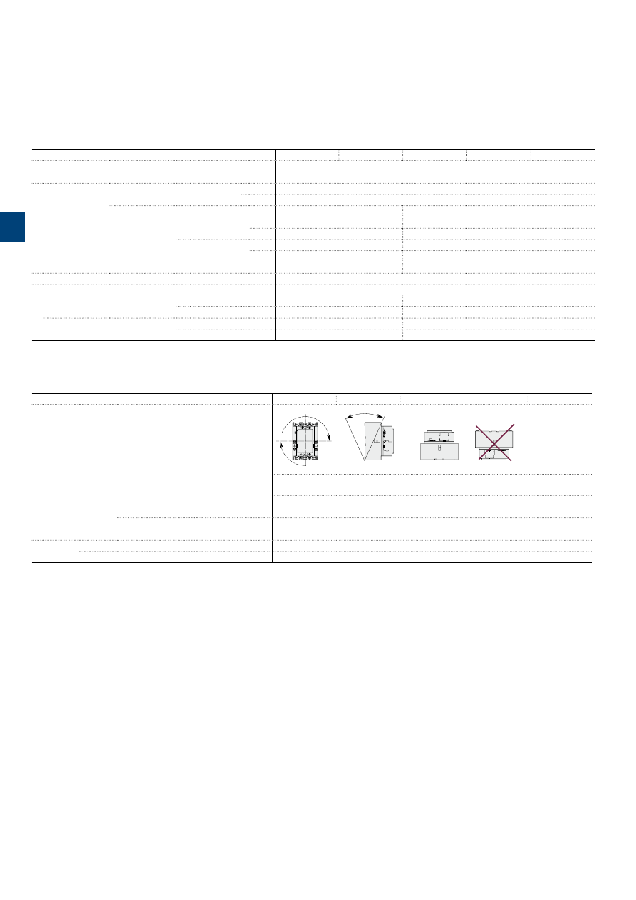
A145 … A300 3-pole contactors
Technical data
Magnet system characteristics
Contactor types
AC operated
A145
A185
A210
A260
A300
Coil operating limits
AC supply
At
θ
≤ 70 °C 0.85...1.1 x Uc
acc. to IEC 60947-4-1
Please also refer to "Mounting characteristics and conditions for use"
AC control voltage
Rated control circuit voltage Uc
at 50 Hz
24…690 V
at 60 Hz
24…690 V
Coil consumption
Average pull-in value 50 Hz
550 VA
1350 VA
60 Hz
600 VA
1550 VA
50/60 Hz
(1)
700 VA / 650 VA
1700 VA / 1550 VA
Average holding value 50 Hz
35 VA / 11 W
60 VA / 16 W
60 Hz
40 VA / 12 W
65 VA / 19 W
50/60 Hz
(1)
44 VA / 13 W
80 VA / 21 W
Drop-out voltage
Approx. 40…65 % of Uc min.
Operating time
Between coil energization and:
N.O. contact closing
13…27 ms
17…35 ms
N.C. contact opening
8…22 ms
12…30 ms
Between coil de-energization and:
N.O. contact opening
5…10 ms
7…13 ms
N.C. contact closing
9…13 ms
10…16 ms
(1) 50/60 Hz coils: see "Voltage code table".
Mounting characteristics and conditions for use
Contactor types
AC operated
A145
A185
A210
A260
A300
Mounting positions
Pos. 5
Pos. 6
Pos. 3
Pos
. 2
Pos. 1
Pos. 1 ± 30°
+30°
-30°
Pos
. 4
Pos. 5
Pos. 6
Pos. 3
Pos
. 2
Pos. 1
Pos. 1 ± 30°
+30°
-30°
Pos
. 4
Max. add-on N.O. or N.C. auxiliary contacts: see accessory fitting details for 3-pole contactor
A145 ... A300
Control voltage / Ambient temperature
Mounting
positions
1, 1±30°, 2, 3, 4, 5
at
θ
≤ 70 °C
0.85 x Uc…1.1 x Uc
6
Unauthorized
Mounting distances
The contactors can be assembled side by side
Fixing
On rail according to IEC 60715, EN 60715
–
By screws (not supplied)
4 x M5
3
/22 |
ABB
1S
FC
10
10
3
9
C
0
2
01
3
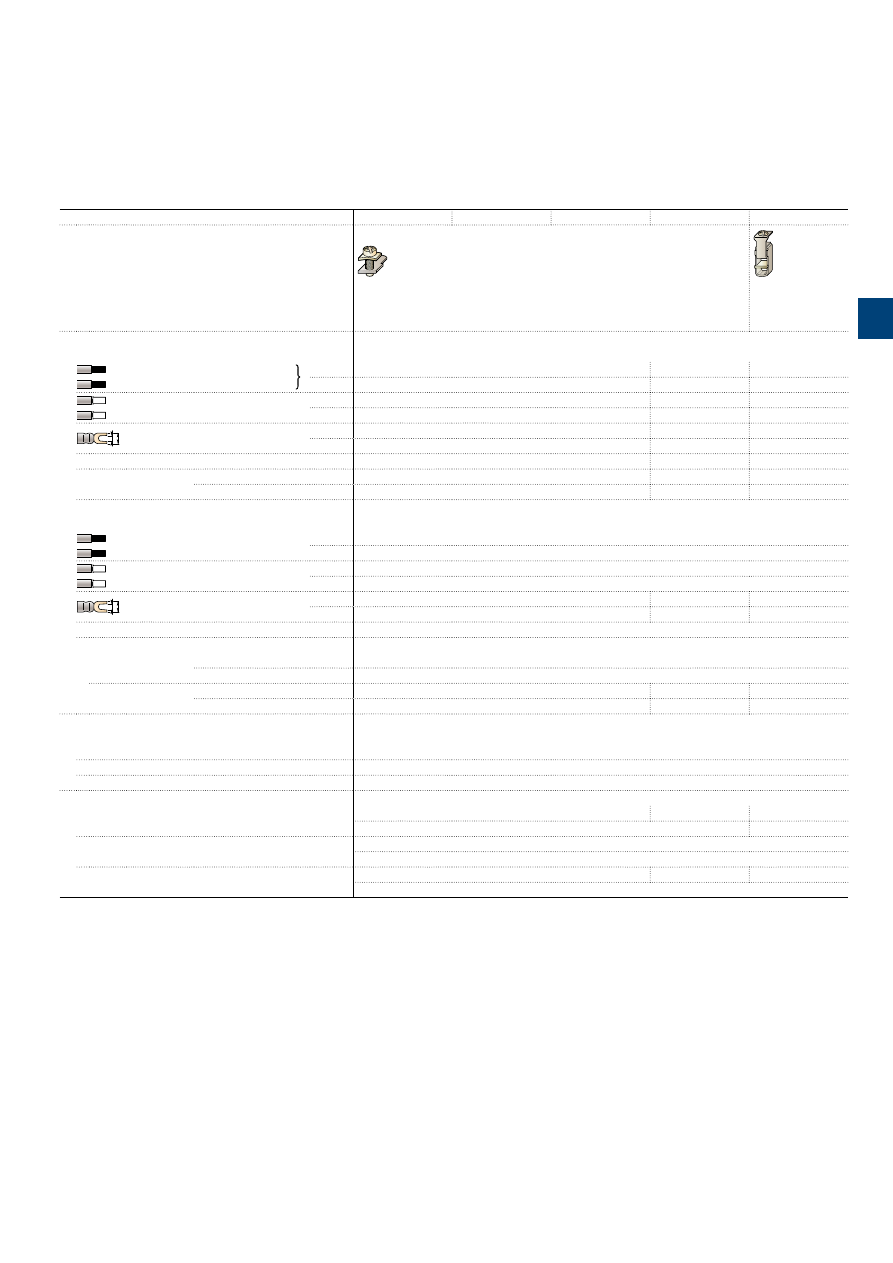
1S
B
C
101
8
6
2S
0
2
01
ABB
|
3
/23
A9 ... A30 3-pole contactors
Technical data
Connecting characteristics
Contactor types
AC operated
A9
A12
A16
A26
A30
Main terminals
Screw terminals with cable clamp
Screw terminals
with double
connector
2 x (5.6 x 6.5 mm)
Connection capacity
(min. ... max.)
Main conductors
(poles)
Rigid
Solid (≤ 4 mm²)
1 x
1...4 mm²
1.5...6 mm²
2.5...16 mm²
Stranded (≥ 6 mm²)
2 x
1...4 mm²
1.5...6 mm²
2.5...16 mm²
Flexible with ferrule
1 x
0.75...2.5 mm²
0.75...4 mm²
2.5...10 mm²
2 x
0.75...2.5 mm²
0.75...4 mm²
2.5...10 mm²
L
l
Bars or lugs
L <
7.7 mm
10 mm
-
l <
3.7 mm
4.2 mm
-
Connection capacity acc. to UL / CSA
1 or 2 x
AWG 18…10
AWG 12…8
AWG 8…4
Tightening torque
Recommended
1 Nm / 9 Ib.in
1.7 Nm / 15 Ib.in
2.3 Nm / 20 Ib.in
Max.
1.2 Nm
2.20 Nm
2.60 Nm
Auxiliary conductors
(built-in auxiliary terminals + coil terminals)
Rigid solid
1 x
1...4 mm²
2 x
1...4 mm²
Flexible with ferrule
1 x
0.75...2.5 mm²
2 x
0.75...2.5 mm²
L
l
Lugs
L <
7.7 mm
(1)
8 mm
l <
3.7 mm
(1)
3.7 mm
Connection capacity acc. to UL / CSA
1 or 2 x
AWG 18...14
Tightening torque
Coil terminals
Recommended
1 Nm / 9 Ib.in
Max.
1.20 Nm
Built-in auxiliary
terminals
Recommended
1 Nm / 9 Ib.in
1.7 Nm / 15 Ib.in
1 Nm / 9 Ib.in
Max.
1.20 Nm
2.20 Nm
1.20 Nm
Degree of protection
acc. to IEC 60947-1 / EN 60947-1 and IEC 60529 / EN 60529
Main terminals
IP20
Coil terminals
IP20
Built-in auxiliary terminals
IP20
Screw terminals
Delivered in open position, screws of unused terminals must be tightened
Main terminals
M3.5
M4
M5
Screwdriver type
Flat Ø 5.5 / Pozidriv 2
Flat Ø 6.5 / Pozidriv 2
Coil terminals
M3.5
Screwdriver type
Flat Ø 5.5 / Pozidriv 2
Built-in auxiliary terminals
M3.5
M4
M3.5
Screwdriver type
Flat Ø 5.5 / Pozidriv 2
(1) L ≤ 8 and l > 3.7 for coil terminals - L ≤ 10 and l > 4.2 for built-in auxiliary terminals.
3
1S
B
C
101
87
9
S
0
2
01
3
/24 |
ABB
A40 ... A110 3-pole contactors
Technical data
Connecting characteristics
Contactor types
AC operated
A40
A50
A63
A75
A95
A110
Main terminals
Screw terminals
with double
connector
2 x (5.6 x 6.5 mm)
Screw terminals
with single
connector
(13 x 10 mm)
Screw terminals
with single
connector
(14 x 14 mm)
Connection capacity
(min. ... max.)
Main conductors
(poles)
Rigid
Solid (≤ 4 mm²)
1 x
2.5...16 mm²
6...50 mm²
10...95 mm²
Stranded (≥ 6 mm²)
2 x
2.5...16 mm²
6...25 mm²
6...35 mm²
Flexible with ferrule
1 x
2.5...10 mm²
6...35 mm²
10…70 mm² (1)
2 x
2.5...10 mm²
6...16 mm²
6…35 mm² (1)
L
l
Bars or lugs
L <
–
–
30 mm (2)
l <
–
–
6 mm
Connection capacity acc. to UL / CSA
1 or 2 x
AWG 8…4
AWG 8…1
AWG 6…2/0
Tightening torque
Recommended
2.30 Nm / 20 lb.in
4.00 Nm / 35 lb.in
8 Nm / 71 lb.in
Max.
2.60 Nm
4.50 Nm
9 Nm
Auxiliary conductors
(built-in auxiliary terminals + coil terminals)
Rigid solid
1 x
1…4 mm²
0.75…2.5 mm²
2 x
1…4 mm²
0.75…2.5 mm²
Flexible with ferrule
1 x
0.75…2.5 mm²
1…2.5 mm²
0.75…2.5 mm²
2 x
0.75…2.5 mm²
L
l
Lugs
L <
8 mm
l <
3.7 mm
Connection capacity acc. to UL / CSA
1 or 2 x
AWG 18...14
Tightening torque
Coil terminals
Recommended
1.00 Nm / 9 lb.in
Max.
1.20 Nm
Built-in auxiliary
terminals
Recommended
1.00 Nm / 9 lb.in
–
–
Max.
1.20 Nm
–
–
Degree of protection
acc. to IEC 60947-1 / EN 60947-1 and IEC 60529 / EN 60529
Main terminals
IP20
IP10
Coil terminals
IP20
Built-in auxiliary terminals
IP20
–
–
Screw terminals
Delivered in open position, screws of unused terminals must be tightened
Main terminals
M5
M6
M8
Screwdriver type
Flat Ø 6.5 / Pozidriv 2
Hexagon socket (s = 4 mm)
Coil terminals
M3.5
Screwdriver type
Flat Ø 5.5 / Pozidriv 2
Built-in auxiliary terminals
M3.5
–
Screwdriver type
Flat Ø 5.5 / Pozidriv 2 –
(1) A95 / A110: use flexible without ferrule.
(2) With LW110 enlargement piece, see "Accessories".
3
A145 … A300 3-pole contactors
Technical data
Connecting characteristics
Contactor types
AC operated
A145
A185
A210
A260
A300
Main terminals
Flat type
E1858D
17.5
ø 8.5
5
E1859D
20
ø 10.2
5
Connection capacity
(min. ... max.)
Main conductors
(poles)
Rigid with
connector
Single for Cu cable
6…185 mm²
16…240 mm²
Single for Al/Cu cable
25…150 mm²
120…240 mm²
Double for Al/Cu cable
–
2 x 95…120 mm²
L
ø
Bars or lugs
L ≤
24 mm
32 mm
Ø >
8 mm
10 mm
Connection capacity acc. to UL / CSA
1 or 2 x
6 - 250 MCM
4 - 500 MCM (1)
Tightening torque
Recommended
18 Nm / 160 Ib.in
28 Nm / 247 lb.in
Max.
20 Nm
30 Nm
Auxiliary conductors
(coil terminals)
Rigid solid
1 x
1…4 mm²
2 x
1…4 mm²
Flexible with ferrule
1 x
0.75…2.5 mm²
2 x
0.75…2.5 mm²
L
l
Lugs
L ≤
8 mm
l >
3.7 mm
Connection capacity acc. to UL / CSA
1 or 2 x
AWG 18…14
Tightening torque
Recommended
1.00 Nm / 9 lb.in
Max.
1.20 Nm
Degree of protection
acc. to IEC 60947-1 / EN 60947-1 and IEC 60529 / EN 60529
Main terminals
IP00
Coil terminals
IP20
Screw terminals
Main terminals
M8
M10
Screws and bolts
Coil terminals (delivered in open position)
M3.5
Screwdriver type
Flat Ø 5.5 mm / Pozidriv 2
(1) With LW110 enlargement piece: see "Accessories".
ABB
|
3
/25
1S
FC
10
115
2C
0
2
01
3
1S
B
C
101
8
8
0
S
0
2
01
3
/26 |
ABB
Built-in auxiliary contacts according to IEC
- Other auxiliary contacts see "Accessories"
Contactor types
AC operated
A9
A12
A16
A26
A30
A40
Rated operational voltage Ue max.
690 V
Rated frequency (without derating)
50/60 Hz
Conventional free air thermal current Ith -
θ
≤ 40 °C
16 A
Ie / Rated operational current AC-15
acc. to IEC 60947-5-1
24-127 V 50/60 Hz
6 A
220-240 V 50/60 Hz
4 A
380-440 V 50/60 Hz
3 A
500 V 50/60 Hz
2 A
690 V 50/60 Hz
2 A
Making capacity AC-15
10 x Ie AC-15 acc. to IEC 60947-5-1
Breaking capacity AC-15
10 x Ie AC-15 acc. to IEC 60947-5-1
Ie / Rated operational current DC-13
acc. to IEC 60947-5-1
24 V DC
6 A / 144 W
48 V DC
2.8 A / 134 W
72 V DC
2 A / 144 W
110 V DC
1.1 A / 121 W
125 V DC
1.1 A / 138 W
220 V DC
0.55 A / 121 W
250 V DC
0.55 A / 138 W
Short-circuit protection device gG type fuse
10 A
Rated short-time withstand current Icw
for 1.0 s
100 A
for 0.1 s
140 A
Minimum switching capacity
17 V / 5 mA
with failure rate acc. to IEC 60947-5-4
≤ 10
-7
for AL40 and TAL40 contactors
Non-overlapping time between N.O. and N.C. contacts
≥ 2 ms
Power dissipation per pole at 6 A
0.1 W
Max. electrical switching frequency
AC-15
1200 cycles/h
DC-13
900 cycles/h
Mechanically linked contacts
Built-in N.O. or N.C. auxiliary contacts and additional N.O. or N.C. auxiliary contacts of 4-pole CA5 are
mechanically linked contacts.
acc. to annex L of IEC 60947-5-1
Mirror contacts
Built-in N.C. auxiliary contacts or additional N.C. auxiliary contacts (CA5, CAL5-11) are mirror contacts.
acc. to annex F of IEC 60947-4-1
Built-in auxiliary contacts according to UL / CSA
Contactor types
AC operated
A9
A12
A16
A26
A30
A40
Max. operational voltage
600 V AC, 600 V DC
Pilot duty
A600, P300
AC thermal rated current
10 A
AC maximum volt-ampere making
7200 VA
AC maximum volt-ampere breaking
720 VA
DC thermal rated current
5 A
DC maximum volt-ampere making-breaking
138 VA
A9 ... A40 3-pole contactors
Technical data
3
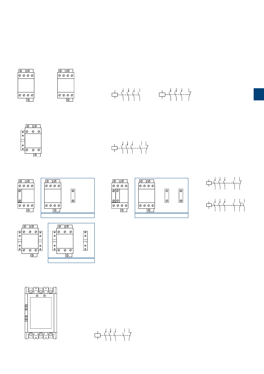
1S
B
C
10
18
81
S
0
2
01
ABB
|
3
/27
A1
A2
1L1
2T1
3L2
4T2
5L3
6T3
13
NO
NO
14
A9 ... A40-30-10
A1
A2
1L1
2T1
3L2
4T2
5L3
6T3
21
NC
NC
22
A9 ... A40-30-01
1
L1
3
L2
5
L3
2
T1
4
T2
6
T3
A1
A2
A2
21
NC
NC
22
A9 ... A40-30-01
1
L1
3
L2
5
L3
2
T1
4
T2
6
T3
A1
A2
A2
13
NO
NO
14
A9 ... A40-30-10
A1
1
L1
2
T1
A2
13X
21X
14X
22X
A2
3
L2
5
L3
4
T2
6
T3
NC
NO
NO
NC
A50 ... A110-30-11
A1
A2
1L1
2T1
3L2
4T2
21X
NC
NC
22X
5L3
6T3
13X
NO
NO
14X
A50 ... A110-30-11
=
+
-1
-2
NC
NO
NC
1
L1
3
L2
5
L3
2
T1
4
T2
6
T3
A1
A2
A2
13
NO
14
21
22
NO
1
L1
3
L2
5
L3
2
T1
4
T2
6
T3
A1
A2
A2
13
NO
14
2-
2-
Combination 11 = A9 ... A40-30-10 + CA5-01
A1
1
L1
2
T1
A2
13X
21X
14X
22X
A2
3
L2
5
L3
4
T2
6
T3
43X
31X
44X
32X
A1
1
L1
2
T1
A2
A2
3
L2
5
L3
4
T2
6
T3
13X
21X
14X
22X
NC
NO
NO
NC
43X
31X
44X
32X
NC
NO
NO
NC
=
+
Combination 22 = A50 ... A75-30-11 + CAL5-11
=
+
+
-1
-2
NC
-3
-4
NO
1
L1
3
L2
5
L3
2
T1
4
T2
6
T3
A1
A2
A2
13
NO
NO
14
21
22
33
34
NO
NC
1
L1
3
L2
5
L3
2
T1
4
T2
6
T3
A1
A2
A2
13
NO
NO
14
2-
2-
3-
3-
Combination 21 = A9 ... A40-30-10 + CA5-01 + CA5-10
13
NO
A1
A2
5L3
6T3
3L2
4T2
1L1
2T1
21
NC
NC
22
NO
14
33
NO
NO
34
13
NO
NO
14
NO
14
Combination 21
A1
A2
5L3
6T3
3L2
4T2
1L1
2T1
21
NC
NC
22
13
NO
NO
14
Combination 11
A1
A2
NO 13X
NC 21X
NC 22X
NO 14X
1L1
3L2
5L3
2T1
4T2
6T3
A145 ... A300-30-11
A1
A2
1L1
2T1
3L2
4T2
21X
NC
NC
22X
5L3
6T3
13X
NO
NO
14X
A145 ... A300-30-11
A145 ... A300 contactors -
AC operated
Standard devices with factory mounted auxiliary contacts
A9 ... A300 3-pole contactors
Terminal marking and positioning
A9 ... A110 contactors -
AC operated
Standard devices without addition of auxiliary contacts
Standard devices with factory mounted auxiliary contacts
Other possible contact combinations with auxiliary contacts added by the user
3
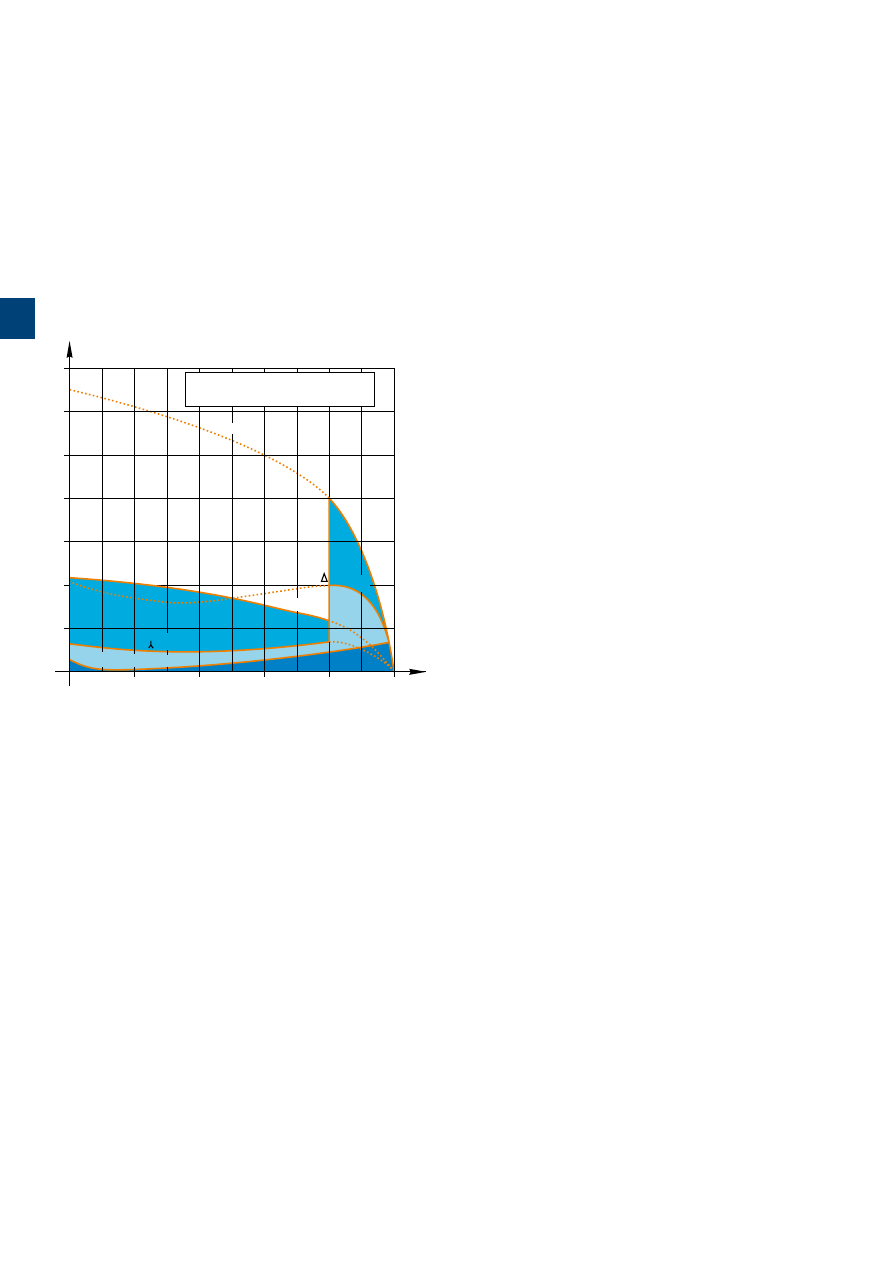
1S
B
C
101
8
8
2S
0
2
01
3
/28 |
ABB
Star-delta starting of three-phase asynchronous motors
Contactor selection
General
Star-delta starting is the most common method to reduce the starting current of a motor. This system can be used on all the
squirrel cage motors, which are normally used in delta connection.
In this type of starting, it is recommended to choose motors having high starting torque i.e. much higher than the resistive
torque in order to reach sufficient high speed when the motor is connected in star.
Star-delta starting
I
/
I
n
T
/
T
n
6
5
4
3
2
1
0
7
20
40
60
100
80
Motor speed (%)
T
r
(resistive torque)
T
(motor)
T (motor
)
I
(star)
I
(delta)
I
= nominal torque
= nominal current
= current;
= torque;
T
n
T
I
n
Technical Data
When starting:
– inrush current is reduced to a third of direct starting current
– motor torque is reduced to a third or even less of direct
starting torque.
Transient current is generated when switching from star to delta con-
nection.
Utilization
During the initial starting phase ("star" connection), the resistive torque
of the driven load must remain, irrespective of speed, less than the
"star" motor torque until "star-delta" switching occurs.
This starting mode is therefore ideal for machines having low starting
torque such as:
– pumps
– centrifugal compressors
– wood-working machines, etc.
In order to prevent a high current peak, at least 85 % of nominal
speed must be reached before switching from star to delta.
Precautions
Motor nominal voltage in delta connection must be equal to that of the
mains.
Example:
A motor for 400 V star-delta starting must be designed for 400 V in "delta" connection. Its usual designation is "400 V / 690 V
motor". The motor must be constructed with 6 terminal windings.
Sequence
Starting is a three-stage process:
1st stage - "Star" connection
Press the "On" button on the control circuit to close the KM2 "star" contactor. The KM1 "line" contactor then closes and the
motor starts. Countdown of programmed starting time (normally 6 to 10 s) then begins.
2nd stage - "Star" to "Delta" switching
When the programmed starting time is over, the KM2 "star" contactor opens.
3rd stage - "Delta" connection
A transition time (or dwelling time) of 50 ms is fixed between opening of the "star" contactor and closing of the "delta" contac-
tor by the use of TE5S timer. This prevents short circuit between "star" and "delta".
Note: An electrical interlock between star and delta is mandatory such as VE 5 or through auxiliary contacts.
Furthermore, in open transition, the current interruption may reach up to 95 ms: it shall be checked that this duration is compatible with the application i.e. mainly if the decreasing
in rotation speed is acceptable during the starting phase.
3
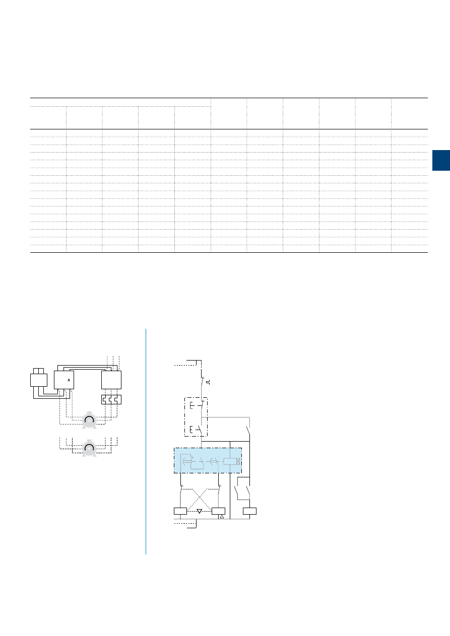
1S
B
C
101
8
8
3
S
0
2
01
ABB
|
3
/29
Star-delta starting of three-phase asynchronous motors
Contactor selection
Rated operational power
(1)
Max. starting
Line
Delta
Star
Overload
Timer
230 V
400 V
415 V
500 V
690 V
time from a
contactor
contactor
contactor
relay
(3)
AC-3
AC-3
AC-3
AC-3
AC-3
cold state
(2)
KM1
KM3
KM2
kW
kW
kW
kW
kW
seconds
Type
Type
Type
Type
Type
4
7.5
7.5
5.5
5.5
15
A9
A9
A9
TA25DU-M
TE5S
5.5
11
11
7.5
7.5
15
A12
A12
A9
TA25DU-M
TE5S
9
15
15
15
11
15
A16
A16
A12
TA25DU-M
TE5S
12.5
22
22
22
15
15
A26
A26
A16
TA25DU-M
TE5S
15
25
25
25
18.5
15
A30
A30
A26
TA25DU-M
TE5S
18.5
37
37
37
37
30
A40
A40
A26
TA42DU-M
TE5S
25
45
45
45
45
30
A50
A50
A30
TA75DU-M
TE5S
30
55
55
63
59
30
A63
A63
A40
TA75DU-M
TE5S
37
63
70
75
63
30
A75
A75
A50
TA75DU-M
TE5S
45
75
75
90
90
20
A95
A95
A75
TA110DU
TE5S
55
90
100
110
132
20
A110
A110
A95
TA110DU
TE5S
75
132
132
160
160
20
A145
A145
A110
TA200DU
TE5S
90
160
160
200
250
20
A185
A185
A145
TA200DU
TE5S
110
200
200
250
315
20
A210
A210
A185
TA450DU
TE5S
140
220
250
295
355
20
A260
A260
A210
TA450DU
TE5S
160
250
250
355
450
20
A300
A300
A260
TA450DU
TE5S
Notes:
(1) Ambient temperature ≤ 55 °C for A9 ... A300
(2) Usual time value = 6...10 s.
(3) The setting current value is: nominal motor current x 0.58.
For motors above 670 kW / 400 V, it is recommended to use Closed Transition Star-Delta starting. Contact your ABB Office for selection.
Power circuit diagram
Control circuit diagrams - Remote control
1
3
5
2
4
6
KM2 / (Y)
1
3
5
2
4
6
KM3 / ( )
1
3
5
2
4
6
KM1 / (L)
L1
L2
L3
W2
V2
U2
W1
V1
U1
W2
V2
U2
W1
V1
U1
1
3
5
2
4
6
E0514D
1
A9 ... A300 contactors
13
14
13
14
Y
KM2
L
KM2
KM1
KM3
KM2
21
22
21
22
O
I
FR1
23
KM1
24
15
16
A1
A2
KT
t1+t2
t1
18
95
96
A1
A2
A1
A2
A1
A2
KM3
KM1
TE5S electronic Timer
Dwelling time = 50 ms
Us
N
KM3 : 3/L2
KM3 : 5/L3
Us
13
14
13
14
Y
KM2
L
KM2
KM1
KM3
KM2
21
22
21
22
O
I
FR1
23
KM1
24
KT
95
96
A1
A2
A1
A2
A1
A2
KM3
KM1
Standard Timer
Without dwelling time
Contactor relay +
TEF
electronic timer
or
C565
electronic timer
Us
N
KM3 : 3/L2
KM3 : 5/L3
Us
A9 ... A300 contactors
3
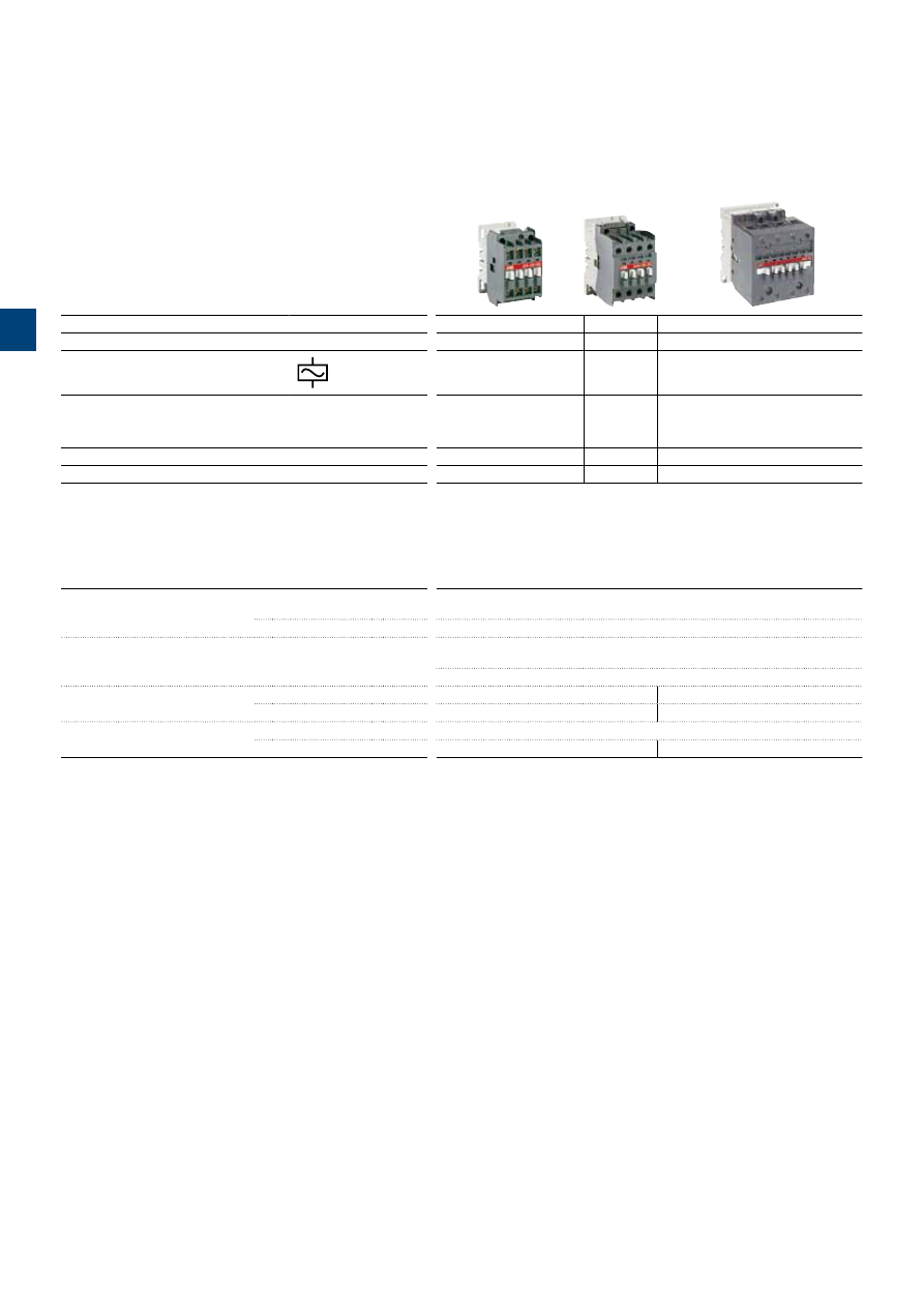
1S
B
C
101
8
8
4
S
0
2
01
4-pole contactors
IEC
AC-1 Rated operational current
θ
≤ 40 °C, 690 V
A
25
30
45
70
100
125
UL/CSA General use rating
600 V
A
21
30
40
65
80
105
AC Control supply
Type
A9
A16
A26
A45
A50
A75
IEC
AC-1 Rated operational current
θ
≤ 40 °C
A
25
30
45
70
100
125
θ
≤ 55 °C
A
22
27
40
60
85
105
θ
≤ 70 °C
A
18
23
32
50
70
85
With conductor cross sectional area
mm
2
2.5
4
6
25
35
50
Rated operational voltage Ue max.
V
690
690
690
1000
1000
1000
Main accessories
Auxiliary contact blocks
Front mounting
CA5-10
(1 x N.O.)
CA5-01
(1 x N.C.)
Side mounting
CAL5-11
(1 x N.O. + 1 x N.C.)
Timers
Electronic
TEF5-ON
TEF5-OFF
TE5S
(for star-delta starters - direct timing - separate mounting)
Interlocking units
Mechanical
VM5-1
Mechanical / Electrical
VE5-1
VE5-2
Surge suppressors
Varistor (AC / DC)
RV5
(24...440 V)
RC Type (AC)
RC5-1
(24...440 V)
RC5-2
(24...440 V)
1S
B
C
101
8
8
4
S
0
2
01
.in
d
d
ABB
|
1
/5
1
3
/30 |
ABB
3
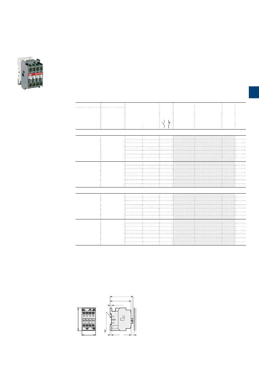
1S
B
C
101
8
57
S
0
2
01
ABB
|
3
/31
1SBC573142F0301
A9-40-00
A9 ... A16 4-pole contactors
25 to 30 A AC-1
AC operated
Main dimensions
mm,
inches
44
1.73"
74
2.91"
68
2.68"
74
2.91"
5.5
0.22"
4
0.16"
10
0.39"
35 mm
EN/IEC 60715
A9, A16
Description
A9 ... A16 4-pole contactors are mainly used for controlling non-inductive or slightly inductive loads (i.e.
resistance furnaces...) and generally for controlling power circuits up to 690 V AC and 440 V DC.
These contactors are of the block type design with:
– 4 main poles
– control circuit: AC operated
– add-on auxiliary contact blocks for front or side mounting and a wide range of accessories.
Ordering details
IEC
UL/CSA
Rated control circuit
voltage
Uc
(1)
Auxiliary
contacts
fitted
Type
Order code
Weight
Pkg
(1 pce)
Rated operational
General use
rating
600 V AC
current
θ
≤ 40 °C
AC-1
A
A
V 50 Hz
V 60 Hz
kg
4 N.O. main poles
25
21
24
24
0 0
A9-40-00
0.340
48
48
0 0
A9-40-00
0.340
110
110…120
0 0
A9-40-00
0.340
220…230
230…240
0 0
A9-40-00
0.340
230…240
240…260
0 0
A9-40-00
0.340
380…400
400…415
0 0
A9-40-00
0.340
400…415
415…440
0 0
A9-40-00
0.340
30
30
24
24
0 0
A16-40-00
0.340
48
48
0 0
A16-40-00
0.340
110
110…120
0 0
A16-40-00
0.340
220…230
230…240
0 0
A16-40-00
0.340
230…240
240…260
0 0
A16-40-00
0.340
380…400
400…415
0 0
A16-40-00
0.340
400…415
415…440
0 0
A16-40-00
0.340
2 N.O. + 2 N.C. main poles
(2)
25
21
24
24
0 0
A9-22-00
0.340
48
48
0 0
A9-22-00
0.340
110
110…120
0 0
A9-22-00
0.340
220…230
230…240
0 0
A9-22-00
0.340
230…240
240…260
0 0
A9-22-00
0.340
380…400
400…415
0 0
A9-22-00
0.340
400…415
415…440
0 0
A9-22-00
0.340
30
30
24
24
0 0
A16-22-00
0.340
48
48
0 0
A16-22-00
0.340
110
110…120
0 0
A16-22-00
0.340
220…230
230…240
0 0
A16-22-00
0.340
230…240
240…260
0 0
A16-22-00
0.340
380…400
400…415
0 0
A16-22-00
0.340
400…415
415…440
0 0
A16-22-00
0.340
(1) Other control voltages see voltage code table.
(2) These contactors are not suitable for a reversing starter or star-delta starter or for controlling a single load from 2 separate supplies.
Please see technical data.
3
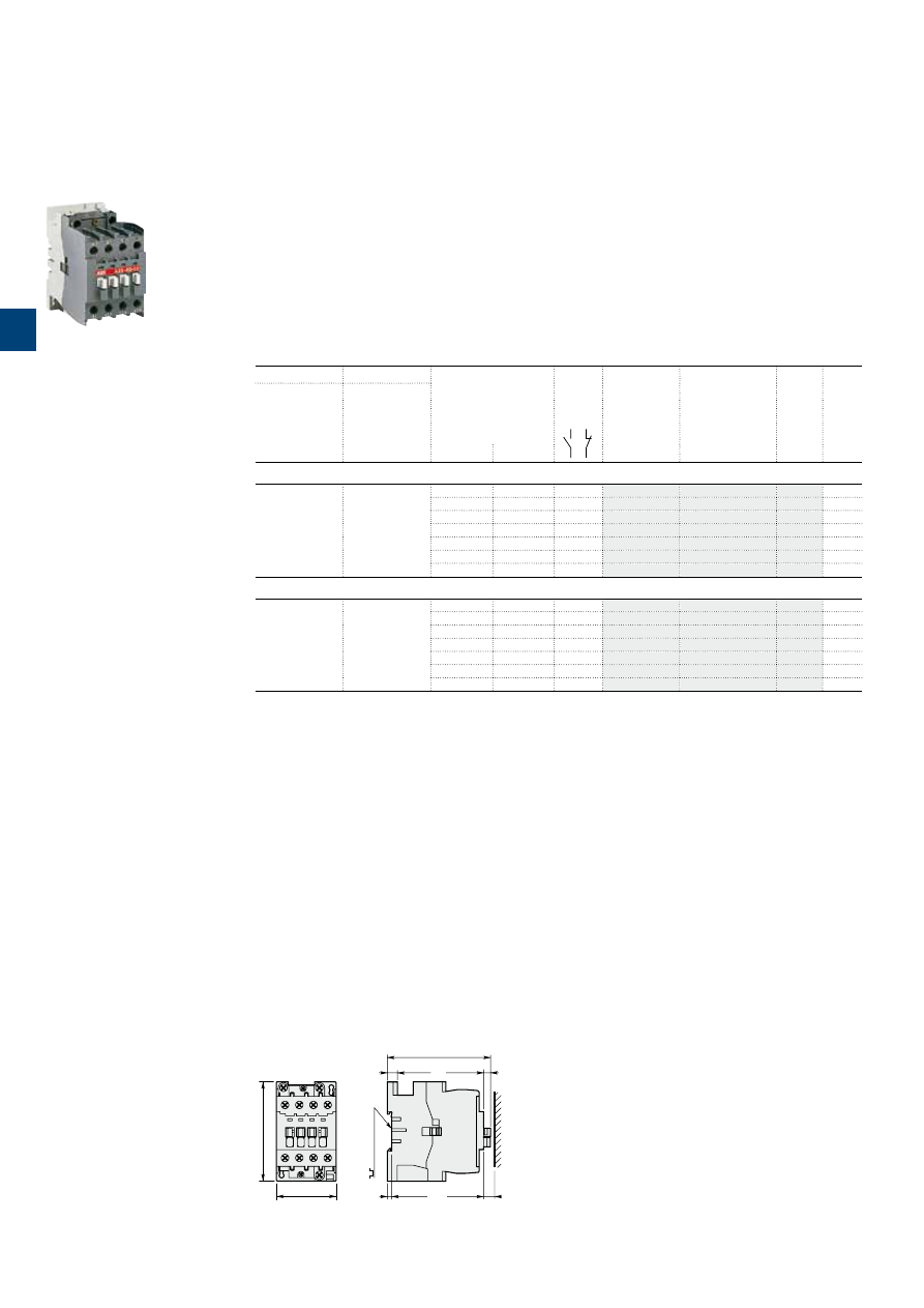
1S
B
C
101
8
6
3
S
0
2
01
3
/32 |
ABB
1SBC573081F0301
A26-40-00
A26 4-pole contactors
45 A AC-1
AC operated
Main dimensions
mm,
inches
54
2.13"
90
3.54"
4
0.16"
10
0.39"
6.3
0.25"
93.6
3.69"
9
0.35"
35 mm
EN/IEC 60715
A26
Description
A26 4-pole contactors are mainly used for controlling non-inductive or slightly inductive loads (i.e. resistance
furnaces...) and generally for controlling power circuits up to 690 V AC and 220 V DC.
These contactors are of the block type design with:
– 4 main poles
– control circuit: AC operated
– add-on auxiliary contact blocks for front or side mounting and a wide range of accessories.
Ordering details
IEC
UL/CSA
Rated control circuit
voltage
Uc
(1)
Auxiliary
contacts
fitted
Type
Order code
Weight
Pkg
(1 pce)
Rated operational
General use
rating
600 V AC
current
θ
≤ 40 °C
AC-1
A
A
V 50 Hz
V 60 Hz
kg
4 N.O. main poles
45
40
24
24
0 0
A26-40-00
0.610
48
48
0 0
A26-40-00
0.610
110
110…120
0 0
A26-40-00
0.610
220…230
230…240
0 0
A26-40-00
0.610
230…240
240…260
0 0
A26-40-00
0.610
380…400
400…415
0 0
A26-40-00
0.610
400…415
415…440
0 0
A26-40-00
0.610
2 N.O. + 2 N.C. main poles
(2)
45
40
24
24
0 0
A26-22-00
0.610
48
48
0 0
A26-22-00
0.610
110
110…120
0 0
A26-22-00
0.610
220…230
230…240
0 0
A26-22-00
0.610
230…240
240…260
0 0
A26-22-00
0.610
380…400
400…415
0 0
A26-22-00
0.610
400…415
415…440
0 0
A26-22-00
0.610
(1) Other control voltages see voltage code table.
(2) These contactors are not suitable for a reversing starter or star-delta starter or for controlling a single load from 2 separate supplies.
Please see technical data.
3
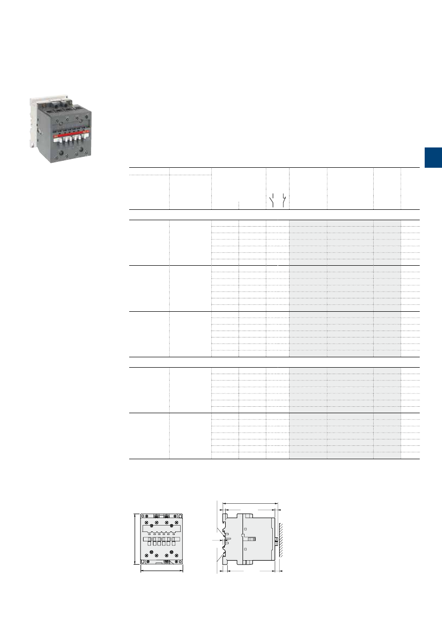
1SBC580873F0301
A45-40-00
A45 … A75 4-pole contactors
70 to 125 A AC-1
AC operated
Description
A45 ... A75 4-pole contactors are mainly used for controlling non-inductive or slightly inductive loads (i.e.
resistance furnaces...) and generally for controlling power circuits up to 690 V AC and 220 V DC.
These contactors are of the block type design with:
– 4 main poles
– control circuit: AC operated
– add-on auxiliary contact blocks for front or side mounting and a wide range of accessories.
Ordering details
IEC
UL/CSA
Rated control circuit
voltage
Uc
(1)
Auxiliary
contacts
fitted
Type
Order code
Weight
Pkg
(1 pce)
Rated operational
current
General use
rating
θ
≤ 40 °C
600 V AC
AC-1
A
A
V 50 Hz
V 60 Hz
kg
4 N.O. main poles
70
65
24
24
0
0
A45-40-00
1.390
48
48
0
0
A45-40-00
1.390
110
110…120
0
0
A45-40-00
1.390
220…230
230…240
0
0
A45-40-00
1.390
230…240
240…260
0
0
A45-40-00
1.390
380…400
400…415
0
0
A45-40-00
1.390
400…415
415…440
0
0
A45-40-00
1.390
100
80
24
24
0
0
A50-40-00
1.390
48
48
0
0
A50-40-00
1.390
110
110…120
0
0
A50-40-00
1.390
220…230
230…240
0
0
A50-40-00
1.390
230…240
240…260
0
0
A50-40-00
1.390
380…400
400…415
0
0
A50-40-00
1.390
400…415
415…440
0
0
A50-40-00
1.390
125
105
24
24
0
0
A75-40-00
1.390
48
48
0
0
A75-40-00
1.390
110
110…120
0
0
A75-40-00
1.390
220…230
230…240
0
0
A75-40-00
1.390
230…240
240…260
0
0
A75-40-00
1.390
380…400
400…415
0
0
A75-40-00
1.390
400…415
415…440
0
0
A75-40-00
1.390
2 N.O. + 2 N.C. main poles
(2)
70
65
24
24
0
0
A45-22-00
1.400
48
48
0
0
A45-22-00
1.400
110
110…120
0
0
A45-22-00
1.400
220…230
230…240
0
0
A45-22-00
1.400
230…240
240…260
0
0
A45-22-00
1.400
380…400
400…415
0
0
A45-22-00
1.400
400…415
415…440
0
0
A45-22-00
1.400
125
105
24
24
0
0
A75-22-00
1.400
48
48
0
0
A75-22-00
1.400
110
110…120
0
0
A75-22-00
1.400
220…230
230…240
0
0
A75-22-00
1.400
230…240
240…260
0
0
A75-22-00
1.400
380…400
400…415
0
0
A75-22-00
1.400
400…415
415…440
0
0
A75-22-00
1.400
(1) Other control voltages see voltage code table.
(2) These contactors are not suitable for a reversing starter or star-delta starter or for controlling a single load from 2 separate supplies.
Please see technical data.
Main dimensions
mm,
inches
A45, A50, A75
92
3.62"
110
4.33"
4
0.16"
6.5
0.26"
6
0.24"
10
0.39"
10
0.39"
75 mm
EN/IEC 60715
35 mm x 15
EN/IEC 60715
119.5
4.7"
ABB
|
3
/33
1S
B
C
101
37
7S
0
2
01
3
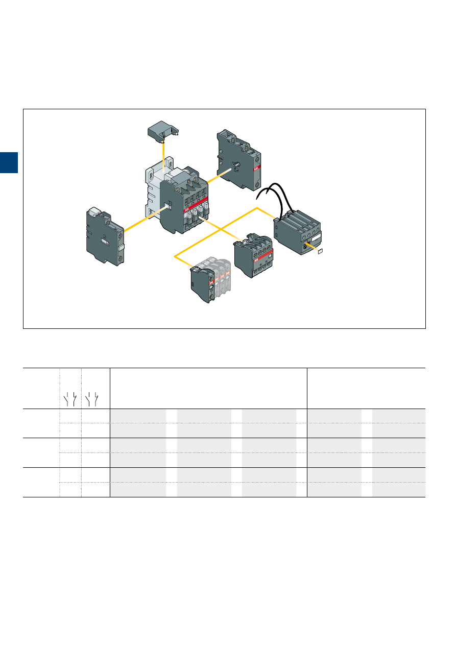
1S
B
C
101
87
3
S
0
2
01
3
/34 |
ABB
A9 … A75 4-pole contactors
Main accessories
Main accessory fitting details
Many configurations of accessories are possible depending on whether these are front-mounted or side-mounted.
Contactor
types
Main
poles
Built-in
auxiliary
contacts
Front-mounted accessories
Side-mounted accessories
Auxiliary contact blocks
Electronic timer
Auxiliary contact blocks
Interlock unit
1-pole CA5
4-pole CA5
TEF5
2-pole CAL5-11
VM5 or VE5
A9, A16
4 0
0 0
1 to 4 x CA5
or
1 x CA5 (4-pole)
or
1 x TEF5
+
1 to 2 x CAL5-11
or
1 x VM5-1 or VE5-1
+ 1 x CAL5-11
2 2
0 0 (1) 1 to 4 x CA5
or
1 x CA5 (4-pole)
or
1 x TEF5
+
1 to 2 x CAL5-11
–
A26
4 0
0 0
1 to 4 x CA5
or
1 x CA5 (4-pole)
or
1 x TEF5
+
1 to 2 x CAL5-11
or
1 x VM5-1 or VE5-1
+ 1 x CAL5-11
2 2
0 0 (1) 1 to 4 x CA5
or
1 x CA5 (4-pole)
or
1 x TEF5
+
1 to 2 x CAL5-11
–
A45 ... A75
4 0
0 0
1 to 6 x CA5
or
1 x CA5 (4-pole)
or
1 x TEF5
+
1 to 2 x CAL5-11
or
1 x VE5-2
+ 2 x 1-pole CA5
+ 2 x CA5 (1-pole)
+ 1 x CAL5-11
2 2
0 0 (2) 1 to 6 x CA5
or
1 x CA5 (4-pole)
or
1 x TEF5
+
1 to 2 x CAL5-11
–
+ 2 x 1-pole CA5
+ 2 x CA5 (1-pole)
(1) 2 N.C. CA5 auxiliary contacts maximum in mounting position 5.
(2) 2 N.C. CA5 auxiliary contacts maximum.
Contactor and main accessories
(other accessories available)
RV5, RC5
Surge suppressor
VE5
Interlock unit
CAL
2-pole auxiliary
contact block
CA5
1-pole auxiliary
contact block
CA5
4-pole auxiliary
contact block
A
contactor
A1
A2
TEF5
Electronic timer
BX4-CA
Protective cover
3
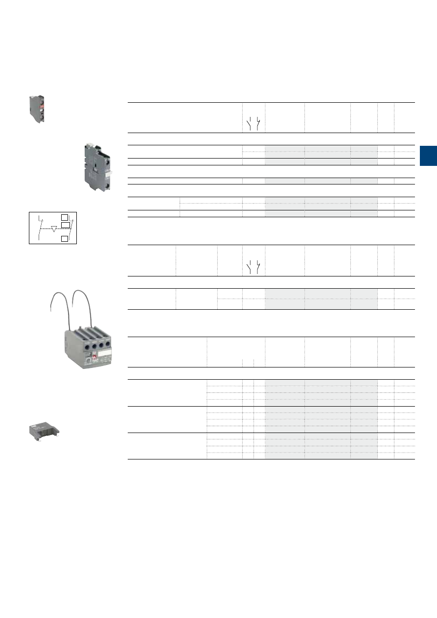
1S
B
C
101
87
4
S
0
2
01
ABB
|
3
/35
A9 … A75 4-pole contactors
Main accessories
Ordering details
(1)
For contactors
Auxiliary
contacts
Type
Order code
Pkg
qty
Weight
(1 pce)
kg
Front-mounted instantaneous auxiliary contact blocks
A9 ... A75
1 –
CA5-10
10
0.014
– 1
CA5-01
10
0.014
A9 ... A75
2 2
CA5-22E
2
0.060
Side-mounted instantaneous auxiliary contact block
A9 … A75
1 1
CAL5-11
2
0.050
Interlock units
A9 ... A26
Mechanical
– –
VM5-1
1
0.066
Mechanical and electrical
– 2
VE5-1
1
0.076
A45 ... A75
Mechanical and electrical
– 2
VE5-2
1
0.146
For contactors
Time delay
range
selected by
switch
Delay
type
Auxiliary
contacts
Type
Order code
Pkg
qty
Weight
(1 pce)
kg
Electronic timers
A9 … A75
0.1...1 s
1...10 s
10...100 s
ON-delay
1 1
TEF5-ON
1
0.065
OFF-delay
1 1
TEF5-OFF
1
0.065
Note: Rated control circuit voltage Uc 24...240 V 50/60 Hz or DC.
For contactors
Rated control circuit
voltage
Uc
Type
Order code
Pkg
qty
Weight
(1 pce)
V
AC DC
kg
Surge suppressors
A9 … A75
24...50
●
●
RV5/50
2
0.015
50...133
●
●
RV5/133
2
0.015
110...250
●
●
RV5/250
2
0.015
250...440
●
●
RV5/440
2
0.015
A9 … A26
24...50
●
–
RC5-1/50
2
0.012
50...133
●
–
RC5-1/133
2
0.012
110...250
●
–
RC5-1/250
2
0.012
250...440
●
–
RC5-1/440
2
0.012
A45 … A75
24...50
●
–
RC5-2/50
2
0.015
50...133
●
–
RC5-2/133
2
0.015
110...250
●
–
RC5-2/250
2
0.015
250...440
●
–
RC5-2/440
2
0.015
(1) See "Main accessory fitting details" table.
CA5-10
1SBC580992F0301
01
02
NC
01
02
NC
VE5-2
Terminal marking and positioning
TEF5-OFF
1SBC101396F0014
CAL5-11
1SBC573752F0301
1SBC574001F0301
RV5/50
3
1S
B
C
101
8
6
4
S
0
2
01
3
/36 |
ABB
A9 ... A26 4-pole contactors
Technical data
Main pole - Utilization characteristics according to IEC
Contactor types
AC operated
A9
A16
A26
Standards
IEC 60947-1 / 60947-4-1 and EN 60947-1 / 60947-4-1
Rated operational voltage Ue max.
690 V
Rated frequency (without derating)
50 / 60 Hz
Conventional free-air thermal current Ith
acc. to IEC 60947-4-1, open contactors,
θ
≤ 40 °C
26 A
30 A
45 A
With conductor cross-sectional area
4 mm²
4 mm²
6 mm²
AC-1 Utilization category
For air temperature close to contactor
Ie / Rated operational current AC-1
θ
≤ 40 °C
25 A
30 A
45 A
Ue max. ≤ 690 V, 50/60 Hz
θ
≤ 55 °C
22 A
27 A
40 A
θ
≤ 70 °C
18 A
23 A
32 A
With conductor cross-sectional area
2.5 mm²
4 mm²
6 mm²
AC-3 Utilization category
For air temperature close to contactor
θ
≤ 55 °C
Ie / Max. rated operational current AC-3
(1)
M
3
3-phase motors
220-230-240 V
9 A
17 A
26 A
380-400 V
9 A
17 A
26 A
415 V
9 A
17 A
26 A
440 V
9 A
16 A
26 A
500 V
9 A
14 A
22 A
690 V
7 A
10 A
17 A
Rated operational power AC-3
(1)
M
3
1500 r.p.m. 50 Hz
1800 r.p.m. 60 Hz
3-phase motors
220-230-240 V
2.2 kW
4 kW
6.5 kW
380-400 V
4 kW
7.5 kW
11 kW
415 V
4 kW
9 kW
11 kW
440 V
4 kW
9 kW
15 kW
500 V
5.5 kW
9 kW
15 kW
690 V
5.5 kW
9 kW
15 kW
Rated making capacity AC-3
10 x Ie AC-3 acc. to IEC 60947-4-1
Rated breaking capacity AC-3
8 x Ie AC-3 acc. to IEC 60947-4-1
Short-circuit protection device for contactors
without thermal overload relay - Motor protection excluded
Ue ≤ 500 V AC - gG type fuse
25 A
32 A
50 A
Rated short-time withstand current Icw
1 s
250 A
300 A
400 A
at 40 °C ambient temperature,
in free air from a cold state
10 s
100 A
140 A
210 A
30 s
60 A
80 A
110 A
1 min
50 A
60 A
90 A
15 min
26 A
30 A
45 A
Power dissipation per pole
Ie / AC-1
0.8 W
1.2 W
1.8 W
Ie / AC-3
0.1 W
0.35 W
0.6 W
Max. electrical switching frequency
AC-1
600 cycle/h
AC-3
1200 cycle/h
(1) For the corresponding kW/A or hp/A values of 1500 r.p.m, 50 Hz or 1800 r.p.m, 60 Hz, 3-phase motors, see "Motor rated operational powers and currents".
Main pole - Utilization characteristics according to UL / CSA
Contactor types
AC operated
A9
A16
A26
Standards
UL 508, CSA C22.2 N°14
Max. operational voltage
600 V
UL / CSA general use rating
600 V AC
21 A
30 A
40 A
With conductor cross-sectional area
AWG 10
AWG 8
Max. electrical switching frequency
For general use
600 cycles/h
3
1S
B
C
101
8
8
5
S
0
2
01
ABB
|
3
/37
A45 ... A75 4-pole contactors
Technical data
Main pole - Utilization characteristics according to IEC
Contactor types
AC operated
A45
A50
A75
Standards
IEC 60947-1 / 60947-4-1 and EN 60947-1 / 60947-4-1
Rated operational voltage Ue max.
1000 V
Rated frequency (without derating)
50 / 60 Hz
Conventional free-air thermal current Ith
acc. to IEC 60947-4-1, open contactors,
θ
≤ 40 °C
100 A
100 A
125 A
With conductor cross-sectional area
35 mm²
35 mm²
50 mm²
AC-1 Utilization category
For air temperature close to contactor
Ie / Rated operational current AC-1
θ
≤ 40 °C
70 A
100 A
125 A
Ue max. ≤ 690 V, 50/60 Hz
θ
≤ 55 °C
60 A
85 A
105 A
θ
≤ 70 °C
50 A
70 A
85 A
With conductor cross-sectional area
25 mm²
35 mm²
50 mm²
AC-3 Utilization category
For air temperature close to contactor
θ
≤ 55 °C
Ie / Max. rated operational current AC-3
(1)
M
3
3-phase motors
220-230-240 V
40 A
53 A
75 A
380-400 V
37 A
50 A
75 A
415 V
37 A
50 A
75 A
440 V
37 A
45 A
70 A
500 V
33 A
45 A
65 A
690 V
25 A
35 A
46 A
1000 V
–
23 A
28 A
Rated operational power AC-3
(1)
M
3
1500 r.p.m. 50 Hz
1800 r.p.m. 60 Hz
3-phase motors
220-230-240 V
11 kW
15 kW
22 kW
380-400 V
18.5 kW
22 kW
37 kW
415 V
18.5 kW
25 kW
40 kW
440 V
22 kW
25 kW
40 kW
500 V
22 kW
30 kW
45 kW
690 V
22 kW
30 kW
40 kW
1000 V
–
30 kW
37 kW
Rated making capacity AC-3
10 x Ie AC-3 acc. to IEC 60947-4-1
Rated breaking capacity AC-3
8 x Ie AC-3 acc. to IEC 60947-4-1
Short-circuit protection device for contactors
without thermal overload relay - Motor protection excluded
Ue ≤ 500 V AC - gG type fuse
80 A
100 A
160 A
Rated short-time withstand current Icw
1 s
1000 A
at 40 °C ambient temperature,
in free air from a cold state
10 s
650 A
30 s
370 A
1 min
250 A
15 min
110 A
110 A
135 A
Power dissipation per pole
Ie / AC-1
2.5 W
5 W
7 W
Ie / AC-3
0.65 W
1.3 W
2 W
Max. electrical switching frequency
AC-1
600 cycles/h
AC-3
600 cycles/h
(1) For the corresponding kW/A or hp/A values of 1500 r.p.m, 50 Hz or 1800 r.p.m, 60 Hz, 3-phase motors, see "Motor rated operational powers and currents".
Main pole - Utilization characteristics according to UL / CSA
Contactor types
AC operated
A45
A50
A75
Standards
UL 508, CSA C22.2 N°14
Max. operational voltage
600 V
UL / CSA general use rating
600 V AC
65 A
80 A
105 A
With conductor cross-sectional area
AWG 6
AWG 4
AWG 2
Max. electrical switching frequency
For general use
600 cycles/h
3
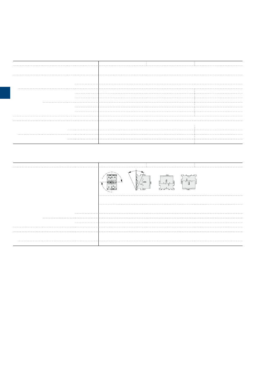
1S
B
C
101
8
6
5
S
0
2
01
3
/38 |
ABB
A9 ... A26 4-pole contactors
Technical data
Magnet system characteristics
Contactor types
AC operated
A9
A16
A26
Coil operating limits
AC supply
at
θ
≤ 55 °C 0.85...1.1 x Uc
Please also refer to "Mounting characteristics and conditions for use"
acc. to IEC 60947-4-1
AC control voltage 50/60 Hz
Rated control circuit voltage Uc
at 50 Hz
24...690 V
at 60 Hz
24...690 V
Coil consumption
Average pull-in value
50 Hz
70 VA
120 VA
60 Hz
80 VA
140 VA
50/60 Hz
(1)
74 VA / 70 VA
125 VA / 120 VA
Average holding value
50 Hz
8 VA / 2 W
12 VA / 3 W
60 Hz
8 VA / 2 W
12 VA / 3 W
50/60 Hz
(1)
8 VA / 2 W
12 VA / 3 W
Drop-out voltage
approx. 40...65 % of Uc
Operating time
Between coil energization and:
N.O. contact closing
10...26 ms
8...21 ms
N.C. contact opening
7...21 ms
6...18 ms
Between coil de-energization and:
N.O. contact opening
4...11 ms
4...11 ms
N.C. contact closing
9...16 ms
7...14 ms
(1) 50/60 Hz coils: see "Coil voltage code table".
Mounting characteristics and conditions for use
Contactor types
AC operated
A9
A16
A26
Mounting positions
Pos. 5
Pos. 6
Pos. 3
Pos
. 2
Pos. 1
Pos. 1 ± 30°
+30°
-30°
Pos
. 4
Max. N.O. or N.C. built-in and add-on N.O. or N.C. auxiliary contacts:
see accessory fitting details for 4-pole contactor A9 ... A26
Control voltage / Ambient temperature
Mounting
positions
1, 1±30°, 2, 3, 4, 5
at
θ
≤ 55 °C
0.85…1.1 x Uc
at
θ
≤ 70 °C
Uc
6
at
θ
≤ 55 °C
0.95…1.1 x Uc
at
θ
≤ 70 °C
unauthorized
Mounting distances
The contactors can be assembled side by side
Fixing
On rail according to IEC 60715, EN 60715
35 x 7.5 mm or 35 x 15 mm
By screws (not supplied)
2 x M4 screws placed diagonally
3
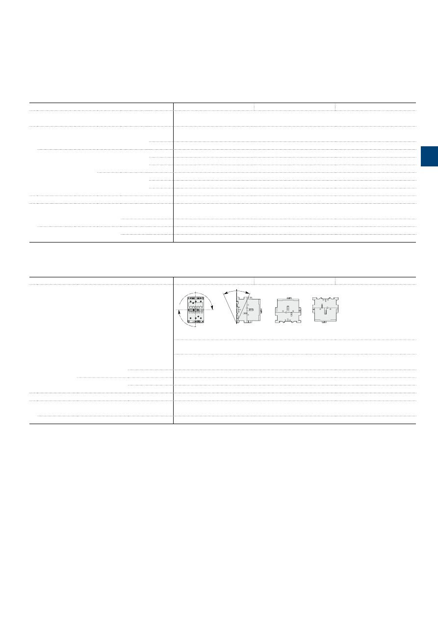
1S
B
C
10
15
5
0
S
0
2
01 - R
ev
. B
ABB
|
3
/39
A45 ... A75 4-pole contactors
Technical data
Magnet system characteristics
Contactor types
AC operated
A45
A50
A75
Coil operating limits
AC supply
At
θ
≤ 55 °C 0.85...1.1 x Uc
acc. to IEC 60947-4-1
Please also refer to "Mounting characteristics and conditions for use"
AC control voltage
Rated control circuit voltage Uc
at 50 Hz
24…690 V
at 60 Hz
24…690 V
Coil consumption
Average pull-in value
50 Hz
180 VA
60 Hz
210 VA
50/60 Hz
(1)
190 VA / 180 VA
Average holding value
50 Hz
18 VA / 5.5 W
60 Hz
18 VA / 5.5 W
50/60 Hz
(1)
18 VA / 5.5 W
Drop-out voltage
approx. 40...65 % of Uc
Operating time
Between coil energization and:
N.O. contact closing
8…27 ms
N.C. contact opening
7…22 ms
Between coil de-energization and:
N.O. contact opening
4…11 ms
N.C. contact closing
7…14 ms
(1) 50/60 Hz coils: see "Coil voltage code table".
Mounting characteristics and conditions for use
Contactor types
AC operated
A45
A50
A75
Mounting positions
Pos. 5
Pos. 6
Pos. 3
Pos
. 2
Pos. 1
Pos. 1 ± 30°
+30°
-30°
Pos
. 4
Pos. 5 unauthorized for A45-22-00, A75-22-00
Max. add-on N.O. or N.C. auxiliary contacts:
see accessory fitting details for 4-pole contactor A45 ... A75
Control voltage / Ambient temperature
Mounting
positions (1)
1, 1±30°, 2, 3, 4, 5
at
θ
≤ 55 °C
0.85…1.1 x Uc
at
θ
≤ 70 °C
Uc
6
at
θ
≤ 55 °C
0.95…1.1 x Uc
at
θ
≤ 70 °C
Unauthorized
Mounting distances
The contactors can be assembled side by side
Fixing
On rail according to IEC 60715, EN 60715
35 x 15 mm or 75 x 25 mm
By screws (not supplied)
2 x M6 screws placed diagonally
(1) For 60 Hz coil voltage: (only for devices fitted with CA 5-.. and CAL 5-11 auxiliary contacts).
– A45-40-00, A50-40-00 and A75-40-00 contactors.
Mounting positions 1 to 5 and ambient temperature ≤ 55 °C: tolerance reduced to 0.9...1.1 Uc (instead of 0.85...1.1 Uc) for coil voltage codes 70 to 79 and 80 to 89.
– A45-22-00 and A75-22-00 contactors.
Mounting positions 1 to 4 and ambient temperature ≤ 55 °C: tolerance reduced to 0.9...1.1 Uc (instead of 0.85...1.1 Uc) for coil voltage codes 70 to 79 and 80 to 89.
For mounting position 6 or ambient temperature of 55 to 70 °C the information given on this page remains applicable.
3
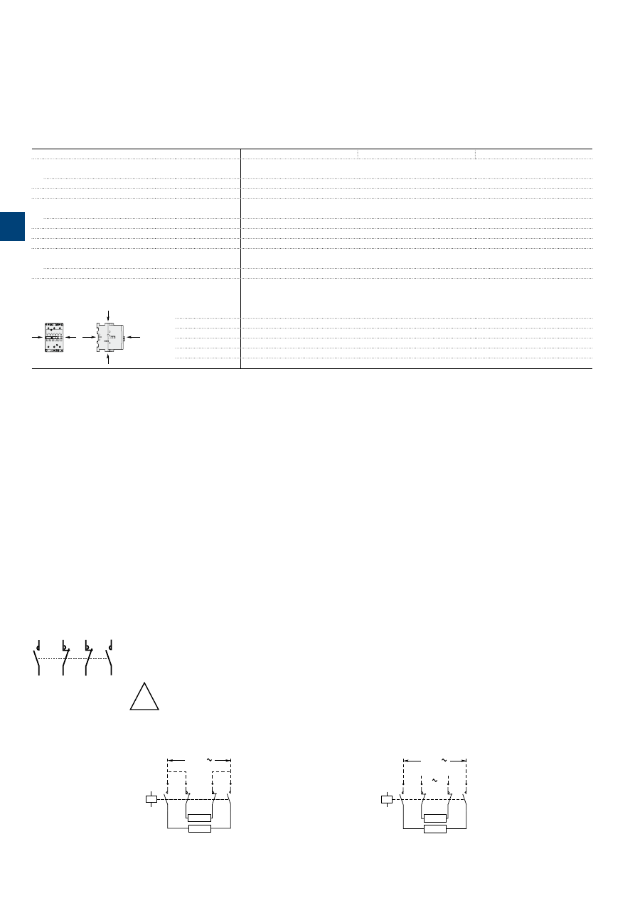
1S
B
C
101
8
6
6
S
0
2
01
3
/40 |
ABB
A9 ... A26 4-pole contactors
Technical data
General technical data
Contactor types
AC operated
A9
A16
A26
Rated insulation voltage Ui
acc. to IEC 60947-4-1
1000 V
acc. to UL / CSA
600 V
Rated impulse withstand voltage Uimp.
8 kV
Ambient air temperature close to contactor
Operation in free air
-40...+70 °C
Storage
-60...+80 °C
Climatic withstand
acc. to IEC 60068-2-30 and 60068-2-11 - UTE C 63-100 specification II
Maximum operating altitude (without derating)
3000 m
Mechanical durability
Number of operating cycles
10 millions operating cycles
Max. switching frequency
3600 cycles/h
Shock withstand
acc. to IEC 60068-2-27 and EN 60068-2-27
Mounting position 1
B2
A
A B1
C2
C1
Shock direction
1/2 sinusoidal shock for 11 ms: no change in contact position, closed or open position
A
20 g
B1
10 g closed position / 5 g open position
B2
15 g
C1
20 g
C2
20 g
3
Remark for 4-pole contactors fitted with 2 N.O. + 2 N.C. main poles
These contactors are suitable for controlling 2 separate circuits, i.e. 2 loads with 2 separate supplies, or 1 circuit comprising
2 separate loads with a single supply (see diagrams below). When the contactor operates there is no mechanical overlapping
between the N.O. poles and the N.C. poles: BREAK before MAKE.
!
These contactors are not suitable for a reversing starter or for controlling a single load from 2 separate supplies.
Block diagrams
– Single supply and 2 separate loads
– 2 separate supplies and 2 separate loads
1
2
R5
R6
R3
R4
7
8
A1
A2
1
2
R5
R6
R3
R4
7
8
Load
Load
Back-up
supply
Main
supply
A1
A2
1
2
R5
R6
R3
R4
7
8
Load
Load
Supply
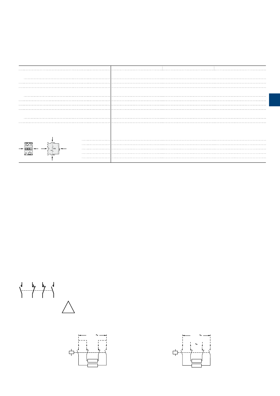
1S
B
C
101
8
8
6
S
0
2
01
ABB
|
3
/41
A45 ... A75 4-pole contactors
Technical data
General technical data
Contactor types
AC operated
A45
A50
A75
Rated insulation voltage Ui
acc. to IEC 60947-4-1
1000 V
acc. to UL / CSA
600 V
Rated impulse withstand voltage Uimp.
8 kV
Ambient air temperature close to contactor
Operation in free air
-40...+70 °C
Storage
-60...+80 °C
Climatic withstand
acc. to IEC 60068-2-30 and 60068-2-11 - UTE C 63-100 specification II
Maximum operating altitude (without derating)
3000 m
Mechanical durability
Number of operating cycles
10 millions operating cycles
Max. switching frequency
3600 cycles/h
Shock withstand
acc. to IEC 60068-2-27 and EN 60068-2-27
Mounting position 1
B2
A
A B1
C2
C1
Shock direction
1/2 sinusoidal shock for 11 ms: no change in contact position, closed or open position
A
20 g
B1
10 g closed position / 5 g open position
B2
15 g
C1
20 g
C2
20 g
3
Remark for 4-pole contactors fitted with 2 N.O. + 2 N.C. main poles
These contactors are suitable for controlling 2 separate circuits, i.e. 2 loads with 2 separate supplies, or 1 circuit comprising
2 separate loads with a single supply (see diagrams below). When the contactor operates there is no mechanical overlapping
between the N.O. poles and the N.C. poles: BREAK before MAKE.
!
These contactors are not suitable for a reversing starter or for controlling a single load from 2 separate supplies.
Block diagrams
– Single supply and 2 separate loads
– 2 separate supplies and 2 separate loads
1
2
R5
R6
R3
R4
7
8
A1
A2
1
2
R5
R6
R3
R4
7
8
Load
Load
Back-up
supply
Main
supply
A1
A2
1
2
R5
R6
R3
R4
7
8
Load
Load
Supply
1S
B
C
101
8
67
S
0
2
01
3
/42 |
ABB
A9 ... A26 4-pole contactors
Technical data
Connecting characteristics
Contactor types
AC operated
A9
A16
A26
Main terminals
Screw terminals with cable clamp
Connection capacity
(min. ... max.)
Main conductors
(poles)
Rigid
Solid (≤ 4 mm²)
1 x
1...4 mm²
1.5...6 mm²
Stranded (≥ 6 mm²)
2 x
1...4 mm²
1.5...6 mm²
Flexible with ferrule
1 x
0.75...2.5 mm²
0.75...4 mm²
2 x
0.75...2.5 mm²
0.75...4 mm²
L
l
Bars or lugs
L <
7.7 mm
10 mm
l <
3.7 mm
4.2 mm
Connection capacity acc. to UL / CSA
1 or 2 x
AWG 18…10
AWG 12…8
Tightening torque
Recommended
1 Nm / 9 Ib.in
1.7 Nm / 15 Ib.in
Max.
1.2 Nm
2.2 Nm
Auxiliary conductors
(coil terminals)
Rigid solid
1 x
1...4 mm²
2 x
1...4 mm²
Flexible with ferrule
1 x
0.75...2.5 mm²
2 x
0.75...2.5 mm²
L
l
Lugs
L <
7.7 mm
(1)
l <
3.7 mm
(1)
Connection capacity acc. to UL / CSA
1 or 2 x
AWG 18...14
Tightening torque
Recommended
1 Nm / 9 Ib.in
Max.
1.2 Nm
Degree of protection
acc. to IEC 60947-1 / EN 60947-1 and IEC 60529 / EN 60529
Main terminals
IP20
Coil terminals
IP20
Screw terminals
Delivered in open position, screws of unused terminals must be tightened
Main terminals
M3.5
M4
Screwdriver type
Flat Ø 5.5 / Pozidriv 2
Coil terminals
M3.5
Screwdriver type
Flat Ø 5.5 / Pozidriv 2
(1) L ≤ 8 and l > 3.7 for coil terminals - L ≤ 10 and l > 4.2 for built-in auxiliary terminals.
3
1S
B
C
101
8
87
S
0
2
01
ABB
|
3
/43
A45 ... A75 4-pole contactors
Technical data
Connecting characteristics
Contactor types
AC operated
A45
A50
A75
Main terminals
Screw terminals with single connector
(13 x 10 mm)
Connection capacity
(min. ... max.)
Main conductors
(poles)
Rigid
Solid (≤ 4 mm²)
1 x
6…50 mm²
Stranded (≥ 6 mm²)
2 x
6…25 mm²
Flexible with ferrule
1 x
6…35 mm²
2 x
6…16 mm²
L
l
Bars or lugs
L <
–
l <
–
Connection capacity acc. to UL / CSA
1 or 2 x
AWG 8…1
Tightening torque
Recommended
4.00 Nm / 35 lb.in
Max.
4.50 Nm
Auxiliary conductors
(coil terminals)
Rigid solid
1 x
1…4 mm²
2 x
1…4 mm²
Flexible with ferrule
1 x
1…2.5 mm²
2 x
0.75…2.5 mm²
L
l
Lugs
L <
8 mm
l <
3.7 mm
Connection capacity acc. to UL / CSA
1 or 2 x
AWG 18…14
Tightening torque
Recommended
1.00 Nm / 9 lb.in
Max.
1.20 Nm
Degree of protection
acc. to IEC 60947-1 / EN 60947-1 and IEC 60529 / EN 60529
Main terminals
IP10
Coil terminals
IP20
Screw terminals
Delivered in open position, screws of unused terminals must be tightened
Main terminals
M6
Screwdriver type
Flat Ø 6.5 / Pozidriv 2
Coil terminals
M3.5
Screwdriver type
Flat Ø 5.5 / Pozidriv 2
3

1S
B
C
101
8
8
8
S
0
2
01
3
/44 |
ABB
A9 ... A75-22-00
A9 ... A75-40-00
A9 ... A75-22-00
A9 ... A75-40-00
1
R3
R5
2
R4
R6
A1
A2
A2
7
8
A1
1
L1
3
L2
5
L3
2
T1
4
T2
6
T3
A2
A2
7
L4
8
T4
A1
A2
1
2
R5
R6
R3
R4
7
8
A1
A2
1L1
2T1
3L2
4T2
5L3
6T3
7L4
8T4
A9 ... A75 4-pole contactors
Terminal marking and positioning
A9 ... A75 contactors -
AC operated
Standard devices without addition of auxiliary contacts
3
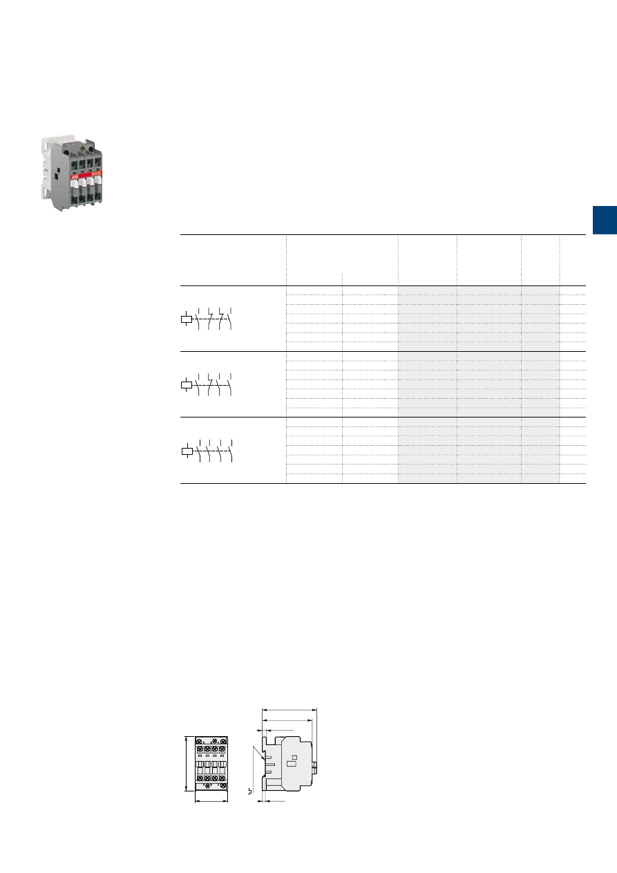
1S
B
C
101
8
5
8
S
0
2
01
ABB
|
3
/45
1SBC573622F0301
N40E
N 4-pole contactor relays
AC operated
Main dimensions
mm,
inches
44
1.73"
74
2.91"
68
2.68"
74
2.91"
5.5
0.22"
4
0.16"
35 mm
EN/IEC 60715
N22E, N31E, N40E
Description
N contactor relays are used for switching auxiliary circuits and control circuits.
These contactor relays are of the block type design with:
– 4 poles. Contactor relays have mechanically linked auxiliary contact elements
– control circuit: AC operated
– add-on auxiliary contact blocks for front or side mounting and a wide range of accessories.
Ordering details
Number of contacts
Rated control circuit
voltage
Uc
(1)
Type
Order code
Weight
Pkg
(1 pce)
V 50 Hz
V 60 Hz
kg
43
NO
NO
44
31
NC
NC
32
21
NC
NC
22
13
NO
NO
14
A1
A2
24
24
N22E
0.340
48
48
N22E
0.340
110
110…120
N22E
0.340
220…230
230…240
N22E
0.340
230…240
240…260
N22E
0.340
380…400
400…415
N22E
0.340
400…415
415…440
N22E
0.340
33
NO
NO
34
21
NC
NC
22
13
NO
NO
14
43
NO
NO
44
A1
A2
24
24
N31E
0.340
48
48
N31E
0.340
110
110…120
N31E
0.340
220…230
230…240
N31E
0.340
230…240
240…260
N31E
0.340
380…400
400…415
N31E
0.340
400…415
415…440
N31E
0.340
43
NO
NO
44
33
NO
NO
34
23
NO
NO
24
13
NO
NO
14
A1
A2
24
24
N40E
0.340
48
48
N40E
0.340
110
110…120
N40E
0.340
220…230
230…240
N40E
0.340
230…240
240…260
N40E
0.340
380…400
400…415
N40E
0.340
400…415
415…440
N40E
0.340
(1) Other control voltages see voltage code table.
3
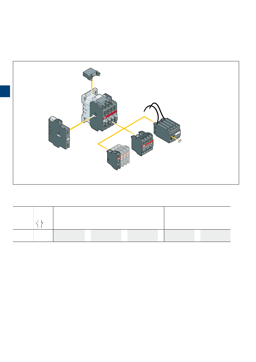
1S
B
C
101
8
8
9
S
0
2
01
3
/46 |
ABB
N 4-pole contactor relays
Main accessories
Main accessory fitting details
Many configurations of accessories are possible depending on whether these are front-mounted or side-mounted.
Contactor
types
Main
poles
Front-mounted accessories
Side-mounted accessories
Auxiliary contact blocks
Electronic timer
Auxiliary contact blocks
1-pole CA5
4-pole CA5
TEF5
2-pole CAL5-11
N
2 2 E (1) 1 to 4 x CA5
or
1 x CA5 (4-pole)
or
1 x TEF5
+
1 to 2 x CAL5-11
3 1 E (1)
4 0 E
(1) 2 N.C. front mounted auxiliary contacts maximum in mounting position 5.
Contactor and main accessories
(other accessories available)
RV5, RC5
Surge suppressor
CAL
2-pole auxiliary
contact block
CA5
1-pole auxiliary
contact block
CA5
4-pole auxiliary
contact block
N
contactor relay
A1
A2
TEF5
Electronic timer
BX4-CA
Protective cover
3
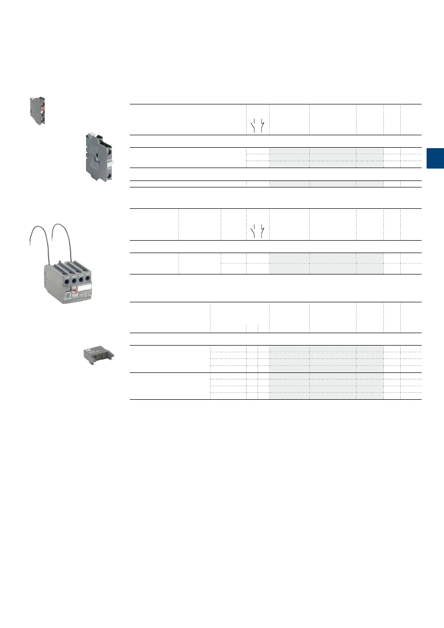
1S
B
C
101
8
9
0
S
0
2
01
ABB
|
3
/47
N 4-pole contactor relays
Main accessories
Ordering details
(1)
For contactors
Auxiliary
contacts
Type
Order code
Pkg
qty
Weight
(1 pce)
kg
Front-mounted instantaneous auxiliary contact blocks
4-pole N
1 –
CA5-10
10
0.014
– 1
CA5-01
10
0.014
2 2
CA5-22N
2
0.060
Side-mounted instantaneous auxiliary contact block
N
1 1
CAL5-11
2
0.050
For contactors
Time delay
range
selected by
switch
Delay
type
Auxiliary
contacts
Type
Order code
Pkg
qty
Weight
(1 pce)
kg
Electronic timers
4-pole N
0.1...1 s
1...10 s
10...100 s
ON-delay
1 1
TEF5-ON
1
0.065
OFF-delay
1 1
TEF5-OFF
1
0.065
Note: Rated control circuit voltage Uc 24...240 V 50/60 Hz or DC.
For contactors
Rated control circuit
voltage
Uc
Type
Order code
Pkg
qty
Weight
(1 pce)
V
AC DC
kg
Surge suppressors
N
24...50
●
●
RV5/50
2
0.015
50...133
●
●
RV5/133
2
0.015
110...250
●
●
RV5/250
2
0.015
250...440
●
●
RV5/440
2
0.015
N
24...50
●
–
RC5-1/50
2
0.012
50...133
●
–
RC5-1/133
2
0.012
110...250
●
–
RC5-1/250
2
0.012
250...440
●
–
RC5-1/440
2
0.012
(1) See "Main accessory fitting details" table.
CA5-10
1SBC580992F0301
CAL5-11
1SBC573752F0301
TEF5-OFF
1SBC101396F0014
1SBC574001F0301
RV5/50
3
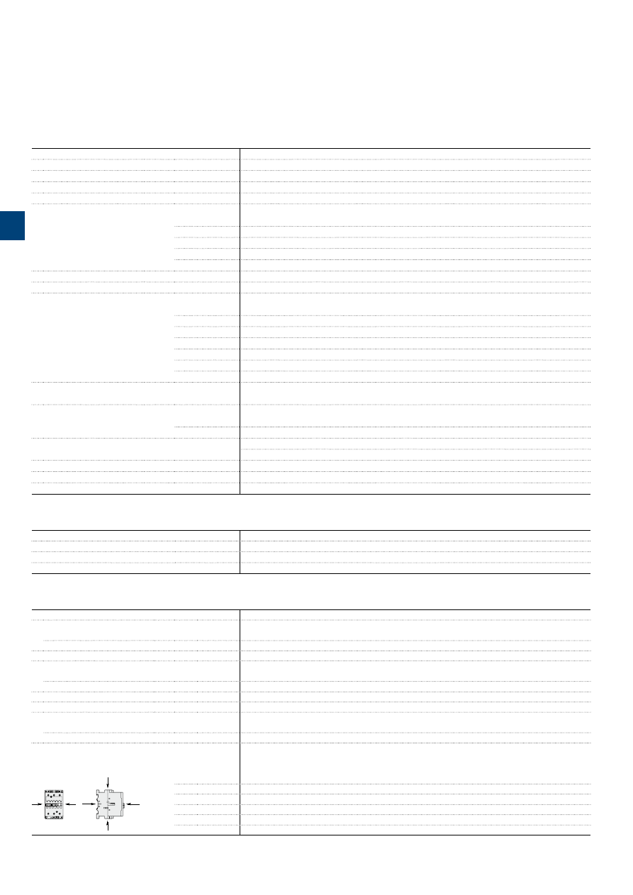
1S
B
C
101
8
6
8
S
0
2
01
3
/48 |
ABB
N contactor relays
Technical data
Contact utilization characteristics according to IEC
Contactor relay types
AC operated
N
Standards
IEC 60947-1 / 60947-5-1 and EN 60947-1 / 60947-5-1
Rated operational voltage Ue max.
690 V
Rated frequency (without derating)
50 / 60 Hz
Conventional free-air thermal current Ith
θ
≤ 40 °C
16 A
Ie / Rated operational current AC-15
acc. to IEC 60947-5-1
24-127 V 50/60 Hz
6 A
230-240 V 50/60 Hz
4 A
400-415 V 50/60 Hz
3 A
500 V 50/60 Hz
2 A
690 V 50/60 Hz
2 A
Rated making capacity AC-15
10 x Ie AC-15 acc. to IEC 60947-5-1
Rated breaking capacity AC-15
10 x Ie AC-15 acc. to IEC 60947-5-1
Ie / Rated operational current DC-13
acc. to IEC 60947-5-1
24 V DC
6 A / 144 W
48 V DC
2.8 A / 134 W
72 V DC
1 A / 72 W
110 V DC
0.55 A / 60 W
125 V DC
0.55 A / 69 W
220 V DC
0.30 A / 66 W
250 V DC
0.30 A / 75 W
Short-circuit protection device for contactors
Ue ≤ 500 V AC - gG type fuse
10 A
Rated short-time withstand current Icw
at 40 °C ambient temperature,
in free air from a cold state
for 1.0 s
100 A
for 0.1 s
140 A
Minimum switching capacity
17 V / 5 mA
with failure rate acc. to IEC 60947-5-4
10
-6
Non-overlapping time between N.O. and N.C. contacts
≥ 2 ms
Power dissipation per pole at 6 A
0.1 W
Max. electrical switching frequency
AC-15
1200 cycles/h
Contact utilization characteristics according to UL / CSA
Contactor relay types
AC operated
N
Standards
UL 508, CSA C22.2 N°14
Max. operational voltage
600 V AC
Pilot duty
A600, Q300
General technical data
Contactor relay types
AC operated
N
Rated insulation voltage Ui
acc. to IEC 60947-5-1
690 V
acc. to UL / CSA
600 V
Rated impulse withstand voltage Uimp.
8 kV
Ambient air temperature
Operation in free air
-40...+70 °C
Storage
-60...+80 °C
Climatic withstand
acc. to IEC 60068-2-30 and 60068-2-11 - UTE C 63-100 specification II
Maximum operating altitude (without derating)
3000 m
Mechanical durability
Number of operating cycles
≥ 20 millions operating cycles
Max. switching frequency
6000 cycles/h
Shock withstand
acc. to IEC 60068-2-27 and EN 60068-2-27
Mounting position 1
B2
A
A B1
C2
C1
Shock direction
1/2 sinusoidal shock for 11 ms: no change in contact position, closed or open position
A
20 g
B1
5 g
B2
15 g
C1
20 g
C2
20 g
3
1S
B
C
101
8
6
9
S
0
2
01
ABB
|
3
/49
N contactor relays
Technical data
Magnet system characteristics
Contactor relay types
AC operated
N
Coil operating limits
AC supply
at
θ
≤ 55 °C 0.85...1.1 x Uc
Please also refer to "Mounting characteristics and conditions for use"
acc. to IEC 60947-4-1
AC control voltage 50/60 Hz
Rated control circuit voltage Uc
at 50 Hz
24...690 V
at 60 Hz
24...690 V
Coil consumption
Average pull-in value
50 Hz
70 VA
60 Hz
80 VA
50/60 Hz
(1)
74 VA / 70 VA
Average holding value
50 Hz
8 VA / 2 W
60 Hz
8 VA / 2 W
50/60 Hz
(1)
8 VA / 2 W
Drop-out voltage
approx. 40...65 % of Uc
Operating time
Between coil energization and:
N.O. contact closing
10...26 ms
N.C. contact opening
7...21 ms
Between coil de-energization and:
N.O. contact opening
4...11 ms
N.C. contact closing
9...16 ms
(1) 50/60 Hz coils: see "Coil voltage code table".
Mounting characteristics and conditions for use
Contactor relay types
AC operated
N
Mounting positions
Pos. 5
Pos. 6
Pos. 3
Pos
. 2
Pos. 1
Pos. 1 ± 30°
+30°
-30°
Pos
. 4
Max. N.O. or N.C. built-in and add-on N.O. or N.C. auxiliary contacts:
see accessory fitting details for contactor relays
Control voltage / Ambient temperature
Mounting
positions
1, 1±30°, 2, 3, 4, 5
at
θ
≤ 55 °C
0.85…1.1 x Uc
at
θ
≤ 70 °C
Uc
6
at
θ
≤ 55 °C
0.95…1.1 x Uc
> 55 °C
unauthorized
Mounting distances
The contactors can be assembled side by side
Fixing
On rail according to IEC 60715, EN 60715
35 x 7.5 mm or 35 x 15 mm
By screws (not supplied)
2 x M4 screws placed diagonally
Connecting characteristics
Contactor relay types
AC operated
N
Main terminals
Screw terminals with cable clamp
Connection capacity
(min. ... max.)
Main conductors
(poles)
Rigid
1 x
1...4 mm²
2 x
1...4 mm²
Flexible with ferrule
1 x
0.75...2.5 mm²
2 x
0.75...2.5 mm²
L
l
Bars or lugs Pole terminals
L <
7.7 mm
l <
3.7 mm
Coil terminals
L <
8 mm
l <
3.7 mm
Connection capacity acc. to UL / CSA
1 or 2 x
AWG 18…14
Tightening torque
Recommended
1 Nm / 9 Ib.in
Max.
1.20 Nm
Degree of protection
acc. to IEC 60947-1 / EN 60947-1 and IEC 60529 / EN 60529
All terminals
IP20
Screw terminals
Delivered in open position, screws of unused terminals must be tightened
All terminals
M3.5
Screwdriver type
Flat Ø 5.5 / Pozidriv 2
3
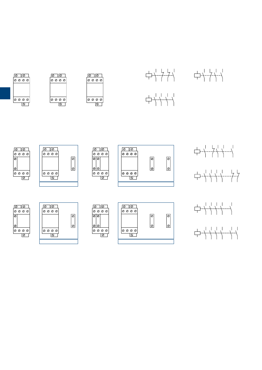
1S
B
C
101
87
0
S
0
2
01
3
/50 |
ABB
N22E
43
NO
NO
44
31
NC
NC
32
21
NC
NC
22
13
NO
NO
14
A1
A2
N40E
43
NO
NO
44
33
NO
NO
34
23
NO
NO
24
13
NO
NO
14
A1
A2
N31E
33
NO
NO
34
21
NC
NC
22
13
NO
NO
14
43
NO
NO
44
A1
A2
A1
A2
13
21
33
43
NO NC NO NO
54
53
NO
NO NC NO NO
14
22
34
44
A2
13
21
33
43
NO NC NO NO
NO
5-
5-
NC NO NO
14
22
34
44
A1
A2
A2
=
+
NO
-3
-4
=
+
+
A1
A2
13
23
33
43
NO NO NO NO
51
52
NC
61
62
NC
NO NO NO NO
14
24
34
44
A2
13
23
33
43
NO NO NO NO
NO NO NO
14
24
34
44
5-
5-
6-
6 -
A1
A2
A2
-1
-2
NC
-1
-2
NC
NO
=
+
-3
-4
NO
NO
NO NO
A1
A2
13
23
33
43
NO
53
54
NO
NO NO NO NO
14
24
34
44
A2
13
23
33
43
NO NO NO NO
NO NO NO NO
14
24
34
44
5-
5-
A1
A2
A2
=
+
+
A1
A2
13
23
33
43
NO NO NO NO
53
54
NO
63
64
NO
NO NO NO NO
14
24
34
44
A2
13
23
33
43
NO NO NO NO
NO NO NO NO
14
24
34
44
5-
5-
6-
6 -
A1
A2
A2
-3
-4
NO
-3
-4
NO
N22E
Combination 41E = N31E + CA5-10
33
NO
NO
34
21
NC
NC
22
13
NO
NO
14
A1
A2
43
NO
NO
44
53
NO
NO
54
Combination 41E
Combination 42E = N40E + CA5-01 + CA5-01
A1
A2
43
NO
NO
44
33
NO
NO
34
23
NO
NO
24
13
NO
NO
14
61
NC
NC
62
51
NC
NC
52
Combination 42E
Combination 50E = N40E + CA5-10
A1
A2
43
NO
NO
44
53
NO
NO
54
33
NO
NO
34
23
NO
NO
24
13
NO
NO
14
Combination 50E
Combination 60E = N40E + CA5-10 + CA5-10
A1
A2
43
NO
NO
44
53
NO
NO
54
63
NO
NO
64
33
NO
NO
34
23
NO
NO
24
13
NO
NO
14
Combination 60E
13
21
31
43
NO NC NC NO
NO NC NC NO
14
22
32
44
A1
A2
A2
N31E
13
21
33
43
NO NC NO NO
NO NC NO NO
14
22
34
44
A1
A2
A2
N40E
13
23
33
43
NO NO NO NO
NO NO NO NO
14
24
34
44
A1
A2
A2
N 4-pole contactor relays
Terminal marking and positioning
N contactor relays -
AC operated
Standard devices without addition of auxiliary contacts
Other possible contact combinations with auxiliary contacts added by the user
3

Notes
ABB
|
3
/51
N2
3
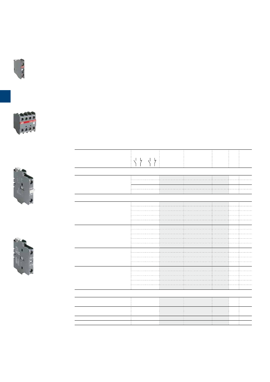
1S
B
C
10
18
91
S
0
2
01
3
/52 |
ABB
Auxiliary contact blocks
Description
The auxiliary contact blocks are used for the operation of auxiliary circuits and control circuits for standard
industrial environments.
Types of auxiliary contact blocks for front mounting:
– CA5
1 or 4-pole block, instantaneous with N.O., N.C. contacts
– CC5
1-pole block, with N.O. leading contact or N.C. lagging contact.
Select the 4-pole auxiliary contact blocks CA5 type, according to the contactor type for compliance with the
standard requirements (see "Terminal marking and positioning").
Types of auxiliary contact blocks for side mounting:
– CAL
2-pole block instantaneous N.O. + N.C. contacts.
For clipping onto the right- and/or left-hand side of the contactors.
The CAL18-11B is a second block for mounting in addition to a first CAL18-11 block, right- and/or left-hand
of the A145 ... A300 contactors.
The auxiliary contact blocks are equipped with screw type connecting terminals delivered open, protected
against accidental direct contact and bear the corresponding function marking.
Ordering details
(1)
For contactors
Auxiliary contacts
Type
Order code
Pkg
qty
Weight
(1 pce)
kg
Front-mounted instantaneous auxiliary contact blocks, 1-pole
A9 ... A110
N 4-pole
1 0
– –
CA5-10
10
0.014
0 1
– –
CA5-01
10
0.014
– –
1 0
CC5-10
10
0.014
– –
0 1
CC5-01
10
0.014
Front-mounted instantaneous auxiliary contact blocks, 4-pole
A9 ... A26-40-00
A9 ... A26-22-00
A45 ... A110
2 2
– –
CA5-22E
2
0.060
3 1
– –
CA5-31E
2
0.060
4 0
– –
CA5-40E
2
0.060
0 4
– –
CA5-04E
2
0.060
1 1
1 1
CA5-11/11E
2
0.060
A9 ... A40-30-10
2 2
– –
CA5-22M
2
0.060
3 1
– –
CA5-31M
2
0.060
1 3
– –
CA5-13M
2
0.060
0 4
– –
CA5-04M
2
0.060
1 1
1 1
CA5-11/11M
2
0.060
A9 ... A40-30-01
2 2
– –
CA5-22U
2
0.060
3 1
– –
CA5-31U
2
0.060
4 0
– –
CA5-40U
2
0.060
0 4
– –
CA5-04U
2
0.060
N 4-pole
2 2
– –
CA5-22N
2
0.060
3 1
– –
CA5-31N
2
0.060
1 3
– –
CA5-13N
2
0.060
0 4
– –
CA5-04N
2
0.060
4 0
– –
CA5-40N
2
0.060
Side-mounted instantaneous auxiliary contact blocks, 2-pole
A9 ... A75
N
1 1
– –
CAL5-11
2
0.050
A9 ... A16
N
– –
1 1
CCL5-11
2
0.050
A95 ... A300
1 1
– –
CAL18-11
2
0.050
A145 ... A300 (2)
1 1
– –
CAL18-11B
2
0.050
(1) For each contactor type, refer to "Accessory fitting details" table.
(2) 2 blocks CAL18-11 + 2 blocks CAL18-11B.
1SBC580992F0301
CA5-10
1SBC573794F0302
CA5-40E
1SBC573752F0301
CAL5-11
1SFC101033F0201
CAL18-11
3
1S
B
C
101
8
9
2S
0
2
01
ABB
|
3
/53
Auxiliary contact blocks
Technical data
Front mounted
Side mounted
Types
1-pole
CA5,
1-pole
CC5,
CAL5-11, CCL5-11
CAL18-11, CAL18-11B
4-pole
CA5
Contact utilization characteristics according to IEC
Standards
IEC 60947-5-1 and EN 60947-5-1
Rated insulation voltage Ui
acc. to IEC 60947-5-1
690 V
Rated operational voltage Ue max.
24...690 V AC
Conventional thermal current Ith -
θ
≤ 40 °C
16 A
Ie / Rated operational current AC-15
acc. to IEC 60947-5-1
24-127 V 50/60 Hz
6 A
220-240 V 50/60 Hz
4 A
380-440 V 50/60 Hz
3 A
500-690 V 50/60 Hz
2 A
Making capacity
10 x Ie AC-15 acc. to IEC 60947-5-1
Breaking capacity
10 x Ie AC-15 acc. to IEC 60947-5-1
Ie / Rated operational current DC-13
acc. to IEC 60947-5-1
24 V DC
6 A / 144 W
48 V DC
2.8 A / 134 W
72 V DC
1 A / 72 W
110 V DC
0.55 A / 60 W
125 V DC
0.55 A / 69 W
220 V DC
0.3 A / 66 W
250 V DC
0.3 A / 75 W
Short-circuit protection device gG type fuse
10 A
Rated short-time withstand current Icw
for 1.0 s
100 A
θ
= 40 °C
for 0.1 s
140 A
Minimum switching capacity
A40 … A75 contactors
17 V / 1 mA
–
with failure rate acc. to IEC 60947-5-4
≤ 10
-7
–
A95 … A110 contactors
24 V / 50 mA
–
24 V / 50 mA (0.5 million of operating cycles)
with failure rate acc. to IEC 60947-5-4
–
–
≤ 10-6
Power dissipation per pole at 6 A
0.1 W
0.15 W
Mechanical durability
Number of operating cycles
10 millions (A9 … A75)
10 millions
5 millions (A95 ... A185)
3 millions (A95 … A110)
3 millions (A210 ... A300)
Max. switching frequency
3600 cycles/h
Electrical durability
Number of operating cycles
see "Electrical durability" curves
Max. switching frequency
AC-15
1200 cycles/h
DC-13
900 cycles/h
Contact utilization characteristics according to UL / CSA
Standards
UL 508, CSA C22.2 N°14
Max. operational voltage
600 V AC, 250 V DC
Pilot duty
A600, Q300
AC thermal rated current
10 A
Connecting characteristics
Connection capacity
(min. ... max.)
Rigid solid
1 x
1...4 mm²
2 x
1...4 mm²
Flexible with ferrule
1 x
0.75...2.5 mm²
2 x
0.75...2.5 mm²
L
l
Lugs
L ≤
7.7 mm
8 mm
l >
3.7 mm
3.7 mm
Connection capacity acc. to UL / CSA
1 or 2 x
AWG 18...14
Tightening torque
1 Nm / 9 lb.in
Degree of protection
Terminals
IP20
acc. to IEC 60947-1 / EN 60947-1 and IEC 60529 / EN 60529
Screw terminals
Delivered in open position, screws of unused terminals must be tightened
All terminals
M3.5
Screwdriver type
Flat Ø 5.5 / Pozidriv 2
3
1S
B
C
101
8
9
3
S
0
2
01
3
/54 |
ABB
Add-on auxiliary contacts
Terminal marking and positioning
31
32
21
22
51
52
41
42
NC
NC
NC
NC
CA5-04M
21
22
11
12
41
42
31
32
NC
NC
NC
NC
CA5-04E
61
62
51
52
81
82
71
72
NC
NC
NC
NC
CA5-04N
1
2
1
2
1
2
1
2
NC
NC
NC
NC
CA5-04U
21
22
13
14
43
44
31
32
NO
NC
NC
NO
CA5-22E
21
22
31
32
43
44
53
54
NO
NO
NC
NC
CA5-22M
61
62
53
54
83
84
71
72
NO
NC
NC
NO
CA5-22N
1
2
3
4
3
4
1
2
NO
NC
NC
NO
CA5-22U
21
22
13
14
43
44
33
34
NO
NC
NO
NO
CA5-31E
21
22
33
34
43
44
53
54
NO
NO
NO
NC
CA5-31M
51
52
63
64
73
74
83
84
NO
NO
NO
NC
CA5-31N
1
2
3
4
3
4
3
4
NO
NC
NO
NO
CA5-31U
61
62
53
54
81
82
71
72
NO
NC
NC
NC
CA5-13N
21
22
13
14
47
48
35
36
NO
NC
NC
NO
CA5-11/11E
33
34
21
22
57
58
45
46
NC NO
NO
NC
CA5-11/11M
53
54
63
64
73
74
83
84
NO
NO
NO
NO
CA5-40N
3
4
3
4
3
4
3
4
NO
NO
NO
NO
CA5-40U
31
32
41
42
NC
NC
53
54
NO
21
22
NC
CA5-13M
13
14
23
24
33
34
43
44
NO
NO
NO
NO
CA5-40E
-1
-2
NC
CA5-01
-5
-6
NC
CC5-01
-7
-8
NO
CC5-10
-3
-4
NO
CA5-10
1-pole auxiliary contacts
21X /
22X /
13X /
14X /
NO
NC
43X
44X
31X
32X
CAL5-11, CAL18-11
(L. h. s. mounted)
25X /
26X /
17X /
18X /
NO
NC
47X
48X
35X
36X
CCL5-11
(L. h. s. mounted)
NC
NO
47X /
48X /
35X /
36X /
25X
26X
17X
18X
CCL5-11
(R. h. s. mounted)
NC
NO
83X /
84X /
71X /
72X /
61X
62X
53X
54X
CAL18-11B
(R. h. s. mounted)
61X /
62X /
53X /
54X /
NO
NC
83X
84X
71X
72X
CAL18-11B
(L. h. s. mounted)
NC
NO
43X /
44X /
31X /
32X /
21X
22X
13X
14X
CAL5-11, CAL18-11
(R. h. s. mounted)
2-pole auxiliary contacts
4-pole auxiliary contacts
3
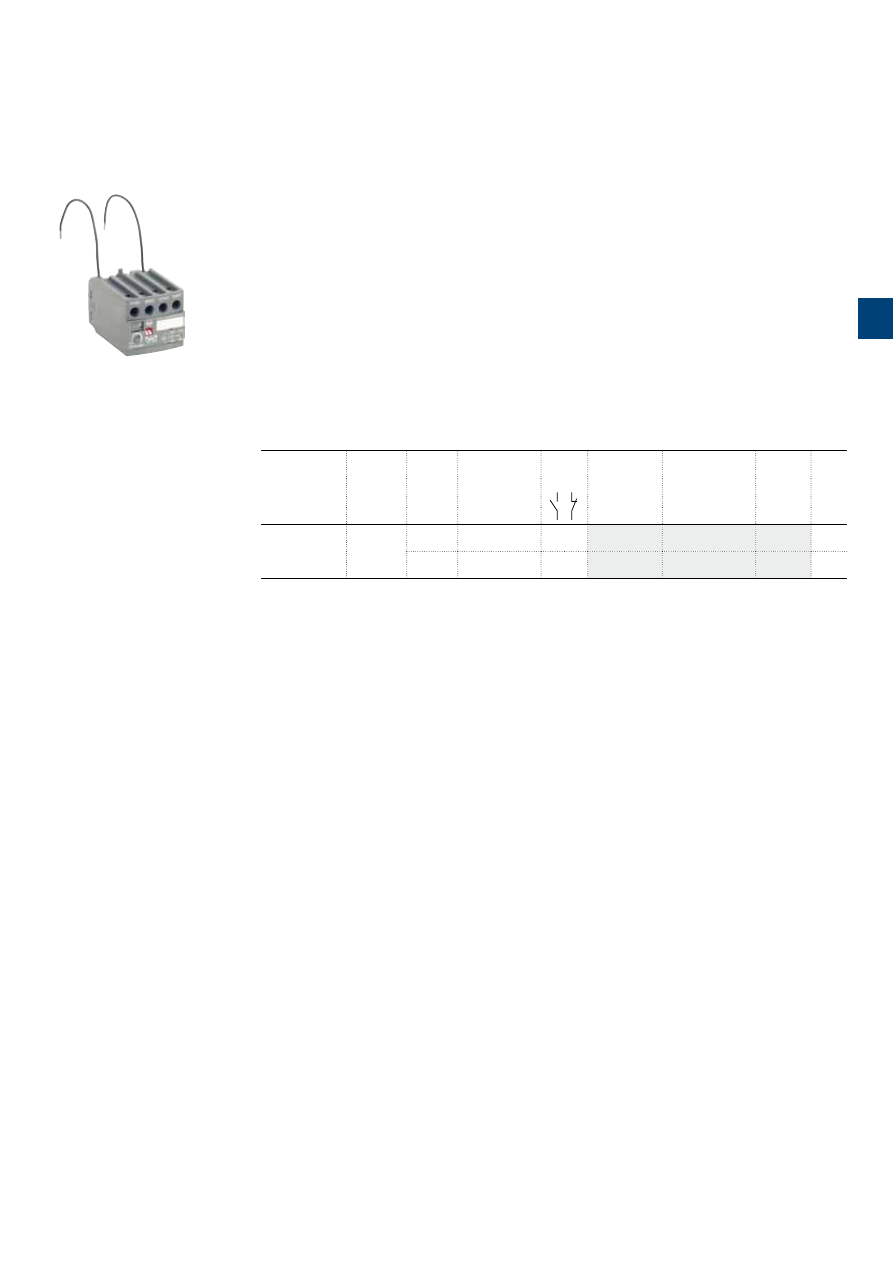
1S
B
C
101
8
9
4
S
0
2
01
ABB
|
3
/55
Electronic timers
Description
TEF5 frontal electronic timers are used for realizing timing function and are available in ON-delay and OFF-
delay versions.
Compact solution in cabinet compared to separate timers
TEF5 electronic timers are front-mounted and locked on A contactors or N contactor relays.
A mechanical indicator allows to show the state of the contactor.
TEF5 electronic timers are supplied by direct wiring to the coil terminals A1 - A2 of the contactor or contac-
tor relay. A varistor is integrated on the timer to offer a built-in protection against surges in the contactor coil.
Available for a wide control voltage range 24...240 V AC / DC
TEF5-ON or TEF5-OFF allow time-delayed functions up to 100 s in 3 distinct time ranges, independently
of the control system. The time delay ranges are selected by a switch and the time delay can be adjusted
by means of a rotary switch. The timing function is activated by closing or opening the device on which the
timer is mounted. The OFF-delay version operates without additional control supply.
Ordering details
For contactors,
contactor relays
Time delay
range
selected by
switch
Delay
type
Rated control
circuit voltage
Uc
Auxiliary
contacts
Type
Order code
Weight
Pkg
(1 pce)
V 50/60 Hz or DC
kg
A9 ... A75
N
0.1...1 s
1...10 s
10...100 s
ON-delay 24...240
1 1
TEF5-ON
0.065
OFF-delay 24...240
1 1
TEF5-OFF
0.065
TEF5-OFF
1SBC101396F0014
3

1S
B
C
101
67
4
S
0
2
01
3
/56 |
ABB
Electronic timers
Technical data
Contact utilization characteristics according to IEC
Types
TEF5-ON
TEF5-OFF
Standards
IEC 60947-5-1 and EN 60947-5-1
Rated insulation voltage Ui
acc. to IEC 60947-5-1
400 V
Rated impulse withstand voltage Uimp
4 kV
Rated operational voltage Ue max.
240 V
Rated frequency (without derating)
50 / 60 Hz
Conventional thermal current Ith -
θ
≤ 40 °C
5 A
Ie / Rated operational current AC-15
acc. to IEC 60947-5-1
24-127 V 50/60 Hz
3 A
220-240 V 50/60 Hz
1.5 A
Making capacity
10 x Ie AC-15 acc. to IEC 60947-5-1
Breaking capacity
10 x Ie AC-15 acc. to IEC 60947-5-1
Ie / Rated operational current DC-13
acc. to IEC 60947-5-1
24 V DC
1 A / 24 W
Short-circuit protection device gG type fuse
6 A
Rated short-time withstand current Icw
for 1.0 s
8 A
θ
= 40 °C
for 0.1 s
8 A
Minimum switching capacity
12 V / 3 mA
with failure rate acc. to IEC 60947-5-4
24 V DC
10
-7
Power dissipation per pole at 3 A
0.1 W
Function diagram
ON-delay
OFF-delay
Uc (A1 - A2)
N.O. (67 - 68)
t
100 ms
min.
150 ms
min.
N.C. (55 - 56)
Uc (A1 - A2)
N.O. (67 - 68)
t
100 ms
min.
1 s
min.
N.C. (55 - 56)
Bistable relay inside.
Before use, once apply Uc then switch it off in order to initialize position of the contacts.
Control circuit voltage
AC control voltage
Rated control circuit voltage Uc
24...240 V AC
50/60 Hz
Average consumption
1.5 mA RMS
1 mA RMS
DC control voltage
Rated control circuit voltage Uc
24...240 V DC
Average consumption
1.5 mA
1 mA
Rated frequency limits
50 / 60 Hz
Supply voltage range
0.85...1.1 x Uc (at
θ
≤ 70 °C)
Overvoltage protection
Varistor included
Time delay range (t) selected by switch
0.1...1 s
1...10 s
10...100 s
On-load reiteration accuracy under constant conditions
≤ 1 %
Minimum ON period
0.1 s
1 s
Recovery time
0.15 s
0.1 s
Ambient air temperature
Operation
-25 °C ... +70 °C
Storage
-40 °C ... +80 °C
Climatic withstand
Category B according to IEC 60947-1 Annex Q
Maximum operating altitude
2000 m
Mounting positions
Acc. to mounting positions permitted on contactors or contactor relays
Shock withstand
1/2 sinusoidal shock for 11 ms: no change in contact position
acc. to IEC 60068-2-27 and EN 60068-2-27
Same as contactor or contactor relay
(Mounting position 1)
Mechanical durability
Number of operating cycles
5 millions operating cycles
Max. switching frequency
3600 cycles/h
1800 cycles/h
Max. electrical switching frequency
AC-15
1200 cycles/h
DC-13
900 cycles/h
3
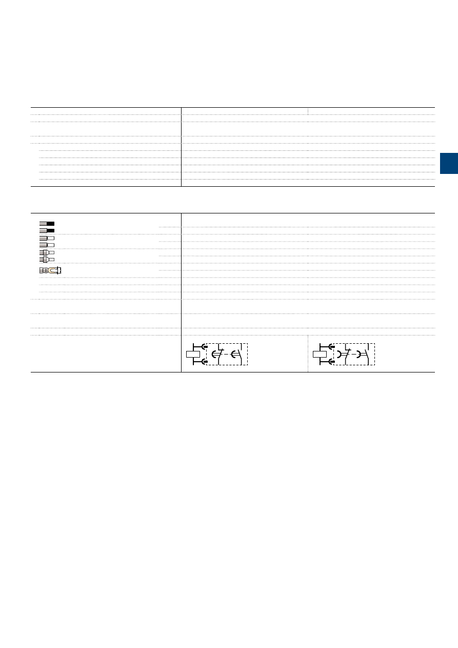
1S
B
C
101
67
4
S
0
2
01
ABB
|
3
/57
Electronic timers
Technical data
Contact utilization characteristics according to UL / CSA
Types
TEF5-ON
TEF5-OFF
Standards
UL 508, CSA C22.2 N°14
Rated insulation voltage Ui
acc. to UL / CSA
300 V
Max. operational voltage
240 V
Pilot duty
B300, R300
AC thermal rated current
5 A
AC maximum volt-ampere making
3600 VA
AC maximum volt-ampere breaking
360 VA
DC thermal rated current
1 A
DC maximum volt-ampere making-breaking
28 VA
Connecting characteristics
Connection capacity
(min. ... max.)
Rigid solid
1 x
1...2.5 mm²
2 x
1...2.5 mm²
Flexible with non insulated ferrule
1 x
0.75...2.5 mm²
2 x
0.75...2.5 mm²
Flexible with insulated ferrule
1 x
0.75...2.5 mm²
2 x
0.75...1.5 mm²
L
l
Lugs
L ≤
8 mm
l >
3.7 mm
Connection capacity acc. to UL / CSA
1 or 2 x
AWG 18...14
Stripping length
10 mm
Tightening torque
1 N.m / 9 lb.in
Degree of protection
acc. to IEC 60947-1 / EN 60947-1 and IEC 60529 / EN 60529 IP20
Screw terminals
Delivered in open position, screws of unused terminals should be tightened
All terminals
M3.5
Screwdriver type
Flat Ø 5.5 / Pozidriv 2
Terminal Marking
A1
A2
56 NC
68 NO
55 NC
67 NO
KM1
A1
A2
56 NC
68 NO
55 NC
67 NO
KM1
3
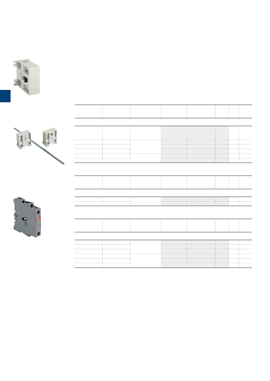
1S
B
C
10
18
95
S0
2
01
3
/58 |
ABB
Mechanical and electrical interlock units
Description
When mounted between two contactors, the mechanical interlock unit prevents one of the contactors from
closing as long as the other contactor is closed.
– VM interlock units for mechanical interlocking of two horizontal or vertical mounted AC or DC operated
contactors
– VE interlock units for mechanical and electrical interlocking of two horizontal mounted AC or DC operated
contactors.
Ordering details
(1)
Left side
contactor
Right side
contactor
Mounting
Type
Order code
Pkg
qty
Weight
(1 pce)
kg
Mechanical interlock units for two horizontal mounted contactors
(2)
A9 ... A40
A9 ... A40
Rail mounting or
mounting plate to be
ordered separately (3)
VM5-1
1
0.066
A9 ... A40
A45 … A110
See table below with
VE5 type
–
–
–
–
A45 … A75
A45 … A110
–
–
–
–
A95 … A185
A45 … A110
–
–
–
–
A95 … A185
A145 … A300
Additional plate
(not supplied)
VM300H
1
0.150
A210 … A300
A145 … A300
VM300H
1
0.150
Up contactor
Down contactor
Mounting
Type
Order code
Pkg
qty
Weight
(1 pce)
kg
Mechanical interlock units for two vertical mounted contactors
(4)
A95 … A185
A145 … A300
Additional plate
(not supplied)
VM300V
1
0.150
A210 … A300
A145 … A300
VM300V
1
0.150
Left side
contactor
Right side
contactor
Mounting
Type
Order code
Pkg
qty
Weight
(1 pce)
kg
Mechanical and electrical interlock units for two horizontal mounted contactors
A9 ... A40
A9 ... A40
Rail mounting or
mounting plate to be
ordered separately (3)
VE5-1
1
0.076
A30 … A75
A45 … A75
VE5-2
1
0.146
A45 ... A75
A30 ... A75
VE5-2
1
0.146
A45 … A75
A95 … A110
Additional plate
(not supplied)
VE5-2 (5)
1
0.146
A95 … A110
A45 … A75
VE5-2 (5)
1
0.146
A95 … A110
A95 … A110
VE5-2
1
0.146
(1) For each contactor type, refer to "Accessory fitting details".
(2) Mechanical durability: VM5-1 = 5 millions cycles, VM300H = 1 million cycles.
(3) Rail mounting for: 2 x A9 ... A40 contactors only
2 x A30, A40 contactors + MMS.
PM26-23 mounting plate for: 2 x A9 ... A26 contactors + MMS.
(4) Mechanical durability: VM300V = 1 million cycles.
(5) The combination of A45 ... A75 contactors interlocked with A95, A110 contactors cannot be mounted on symmetrical rail
(75 mm, IEC/EN 60715).
1SBC580411F0301
VM300H
1SBC580411F0301
VM300V
1SBC572822F0301
VE5-1
3
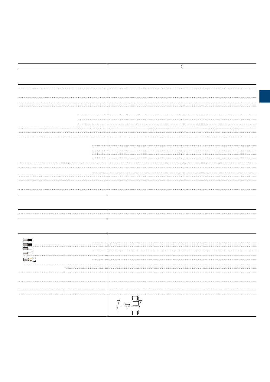
1S
B
C
101
8
9
6
S
0
2
01
ABB
|
3
/59
Mechanical and electrical interlock units
Technical data
Types
VE5-1
VE5-2
Contact utilization characteristics according to IEC
Standards
IEC 60947-5-1 and EN 60947-5-1
Rated insulation voltage Ui
acc. to IEC 60947-5-1
690 V
Rated operational voltage Ue max.
24...690 V
Conventional thermal current Ith -
θ
≤ 40 °C
16 A
Ie / Rated operational current AC-15
acc. to IEC 60947-5-1
24-127 V 50/60 Hz
6 A
220-240 V 50/60 Hz
4 A
380-440 V 50/60 Hz
3 A
500-690 V 50/60 Hz
2 A
Making capacity
10 x Ie AC-15 acc. to IEC 60947-5-1
Breaking capacity
10 x Ie AC-15 acc. to IEC 60947-5-1
Ie / Rated operational current DC-13
acc. to IEC 60947-5-1
24 V DC
6 A
48 V DC
2.8 A
72 V DC
1 A
125 V DC
0.55 A
250 V DC
0.3 A
Short-circuit protection device - gG type fuse
10 A
Rated short-time withstand current Icw
for 1.0 s
100 A
θ
= 40 °C
for 0.1 s
140 A
Power dissipation per pole at 6 A
0.15 W
Mechanical durability
Number of operating cycles
5 millions operating cycles
Max. switching frequency
600 cycles/h
Utilization characteristics according to UL / CSA
Standards
UL 508, CSA C22.2 N°14
Max. operational voltage
600 V
Connecting characteristics
Connection capacity
(min. ... max.)
Rigid solid
1 x
1...4 mm²
2 x
1...4 mm²
Flexible with ferrule
1 x
0.75...2.5 mm²
2 x
0.75...2.5 mm²
L
l
Lugs
L <
8 mm
l >
3.5 mm
Tightening torque
Recommended
1 Nm
Max.
1.2 Nm
Degree of protection
acc. to IEC 60947-1 / EN 60947-1 and IEC 60529 / EN 60529
IP20
Screw terminals
Delivered in open position, screws of unused terminals must be tightened
All terminals
M3.5
Screwdriver type
Flat Ø 5.5 / Pozidriv 2
Terminal marking
01
02
NC
E0085D
1
01
02
NC
Technical note: when, during switching, the arc time is estimated to more than 40 ms, the closing signal of one of the two contactors must be delayed with respect to the opening
signal of the other contactor in order to prevent a short-circuit.
Use a TEF5 or TE5S electronic timer according to application use with time lapse for A contators.
3
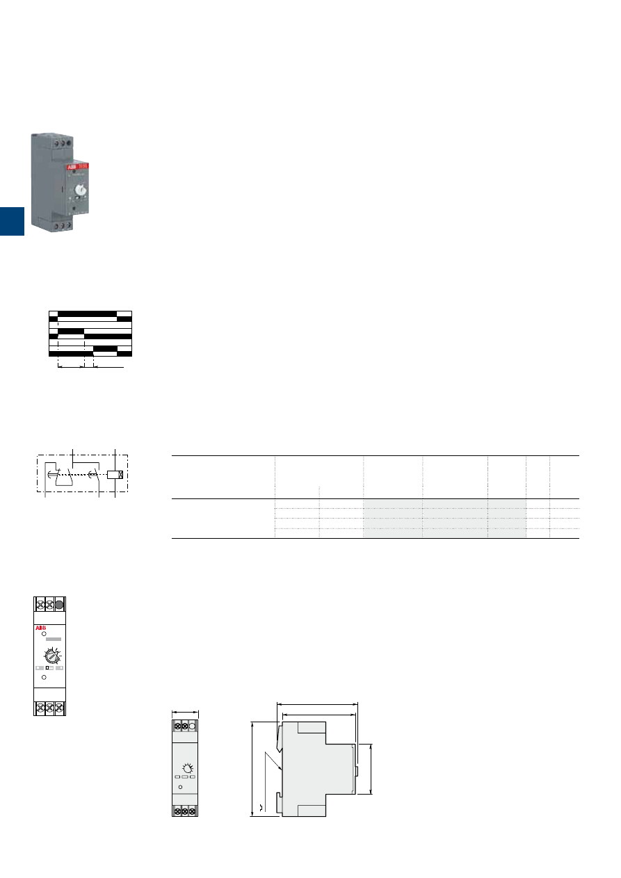
1S
B
C
10
15
2
3
S
0
2
01
3
/60 |
ABB
Electronic timer for star-delta starters
Description
When used in star-delta starters, the TE5S lags the star connection and provides a lapse of 50 ms before
the switch over to delta connection.
According to the type of device chosen, the electronic circuit has a 24 V AC / DC, 110 to 120 V AC,
220 to 240 V AC or 380 to 440 V AC supply. An output relay with reversing contact ensures high current
switching. A two-position switch allows selection of one of the two time delay ranges: 0.8 to 8 s or 6 to
60 s. The 0.1 to 1.0 graduated button allows an initial setting without steps within the previously selected
range which can then be adjusted using a chronometer.
Note
: We recommend that you allow for temperature drift for the final adjustment of the time delay setting.
Drift: -0.2 % per °C.
For example, a setting made at 20 °C will yield a time delay shorter by 7 % at 55 °C in a cubicle (-0.2 %
per °C i.e. -0.2 x 35 = -7 %).
Regardless of these settings the TE5S provides a fixed "lapse" of 50 ms between the opening of contact
15-16 and the closing of contact 15-18. This time delay prevents from arc short-circuit during star to delta
switching.
Operation
On energization, the green U indicator light (voltage applied) comes on. Contact 15-16 then immediately
moves to the closed position.
Count-down of the programmed time immediately commences. When the time delay has elapsed, contact
15-16 opens and at the same time the 50 ms lapse, t2, begins after which contact 15-18 moves to the
closed position. The yellow R indicator light comes on.
On de-energization, the U and R indicator lights go out and, after the 250 ms resetting time, the device is
ready for a new cycle.
Mounting
On 35 x 7.5 mm or 35 x 15 mm mounting rail according to IEC/EN 60715.
Ordering details
For contactors
Rated control circuit
voltage
Uc
Type
Order code
Pkg
qty
Weight
(1 pce)
V 50/60 Hz
V DC
kg
A9 ... A300
24
24
TE5S-24
1
0.080
110...120
–
TE5S-120
1
0.080
220...240
–
TE5S-240
1
0.080
380...440
–
TE5S-440
1
0.080
Main dimensions
mm,
inches
23
0.91"
65
2.56"
75
2.95"
35 mm EN/IEC 60715
45
1.77"
85
3.35"
1SBC575582F0302
TE5S...
U
15-16
t
1
(
t
2
= 50ms)
15-18
R
E0719D1
t
2
Chart
t1
t1+t2
A1
A2
16
15
18
E0718D
Equivalent diagram
TE5S
R
Star-Delta Timer
U
x 0.1
0.5
1.0
8s
t1
A1
15
A1 15
16
A2
18
16
A2
18
60s
E0720D1
Uc=
Front face
3
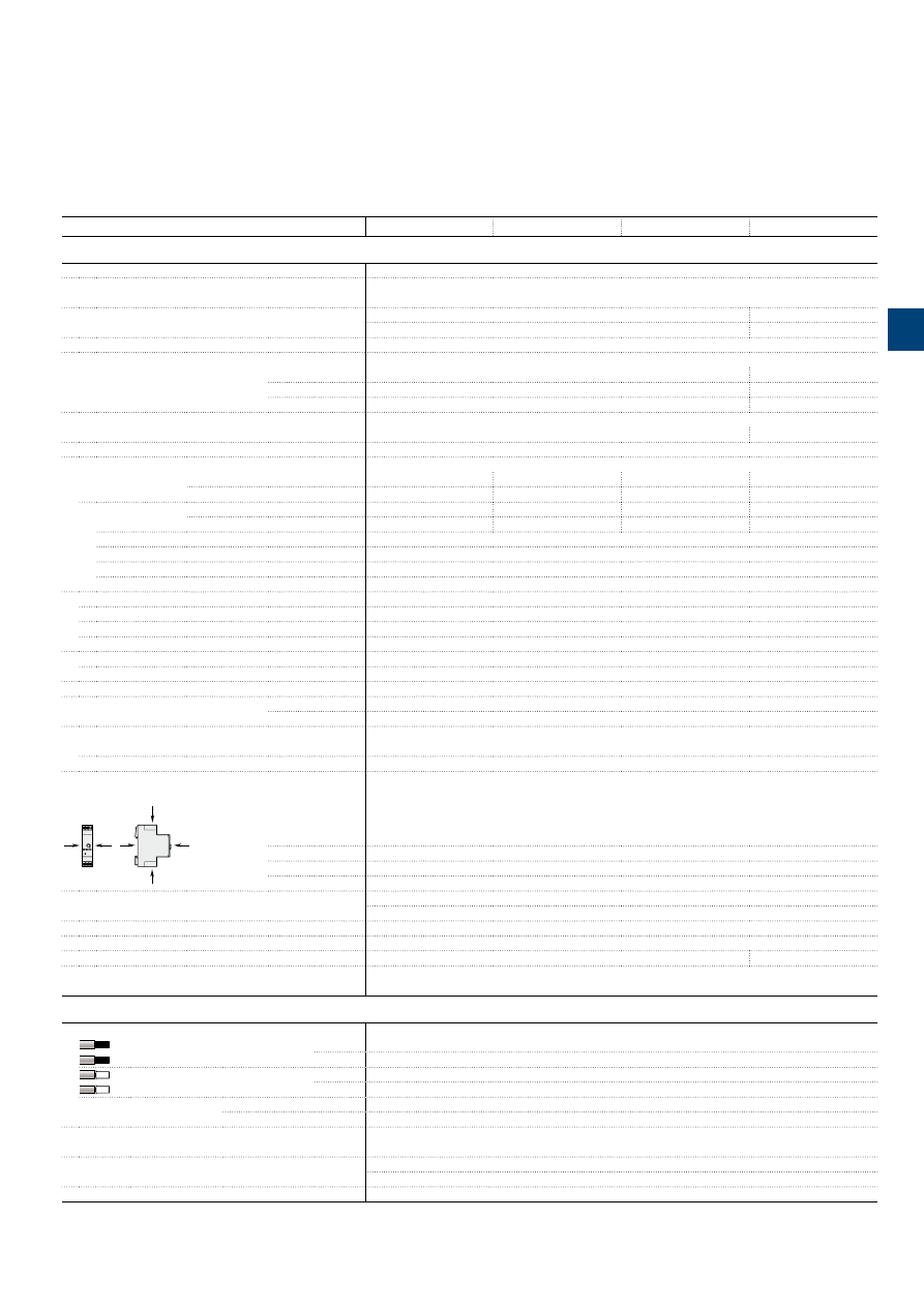
1S
B
C
10
13
26
S
0
2
01 - R
ev
. A
ABB
|
3
/61
Electronic timer for star-delta starters
Technical data
Types
TE5S-24
TE5S-120
TE5S-240
TE5S-440
Utilization characteristics according to IEC
Standards
IEC 60947-5-1 and EN 60947-5-1
Rated insulation voltage Ui
acc. to IEC 60947-5-1
440 V
Rated operational voltage Ue max.
24 V DC
–
24…240 V AC
440 V AC
Conventional free air thermal current Ith
10 A
Ie / Rated operational current AC-15
acc. to IEC 60947-5-1
24-120 V 50/60 Hz
5 A
–
220-240 V 50/60 Hz
4 A
–
380-440 V 50/60 Hz
–
3 A
Ie / Rated operational current DC-13
acc. to IEC 60947-5-1
24 V DC
4 A
–
Short-circuit protection device - gG type fuse
10 A
Control circuit voltage
AC control voltage
Rated supply voltage Uc
24 V AC
110…120 V AC
220…240 V AC
380…440 V AC
50/60 Hz
Average consumption
1.5 VA
3.5 VA
6.5 VA
12.5 VA
DC control voltage
Rated supply voltage Uc
24 V DC
–
–
–
Average consumption
0.7 W
–
–
–
Rated frequency limits
48…63 Hz
Supply voltage range
0.85…1.1 x Uc
Overvoltage protection
Built-in varistor
Load factor
100 %
Time delay range (t1) selected by switch
0.8…8 s and 6…60 s
Temperature drift
-0.2 % per °C
Mechanical setting accuracy
±15 % of the setting range
On-load reiteration accuracy under constant conditions
±2 % after 1 million operating cycles
Minimum time lapse (t2)
50 ms
Minimum time lapse after 1 million of operating cycles
40 ms
Resetting time
(max.)
250 ms
Front panel display
green indicator light
Energization
yellow indicator light
Output relay activated
Ambient air temperature
Operation
-25…+60 °C
Storage
-40…+85 °C
Shock withstand
acc. to IEC 60068-2-27 and EN 6006-2-27
B
A
A B
C
C
E0863D
Shock direction
A
20 g / 11 ms
B
15 g / 11 ms
C
20 g / 11 ms
Vibration withstand
10 to 300 Hz in the 3 directions
acc. to IEC 60068-2-6 and EN 60068-2-6
3 g
Mechanical durability
5 millions operating cycles
Electrical durability
1 million operating cycles
On-load maximum switching frequency
720 cycles/h
600 cycles/h
Fixing
On rail according to IEC 60715, EN 60715
35 x 7.5 mm or 35 x 15 mm
Connecting characteristics
Connection capacity
(min. ... max.)
Rigid solid
1 x
1...2.5 mm²
2 x
1...2.5 mm²
Flexible with ferrule
1 x
0.75...2.5 mm²
2 x
0.75...2.5 mm²
Tightening torque
Recommended
0.6 Nm
Max.
0.8 Nm
Degree of protection
acc. to IEC 60947-1 / EN 60947-1 and IEC 60529 / EN 60529 IP20
Screw terminals
Delivered in open position, screws of unused terminals must be tightened
All terminals
M2.5
Screwdriver type
Flat Ø 4 / Pozidriv 1
3
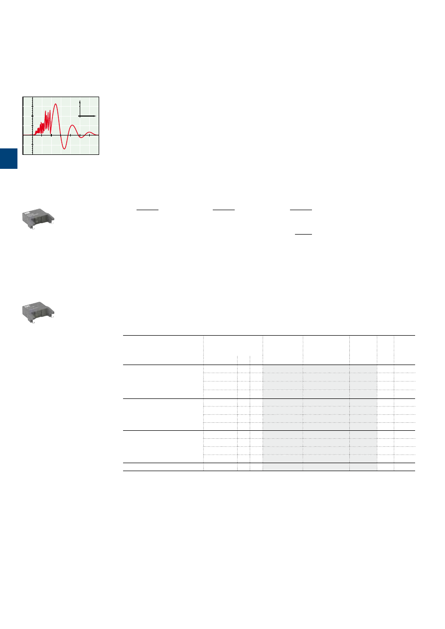
1S
B
C
101
8
9
9
S
0
2
01
3
/62 |
ABB
Surge suppressors for contactor coils
0
1000
100
(V)
T
(
µ
s)
0
1000
100
A 884D
RV5/50
RC5-1/50
1SBC573891F0301
1SBC574001F0301
Description
The operation of inductive circuits causes overvoltages, in particular on opening of the contactor coil.
The electromagnetic energy stored in the coil during contactor closing is restored on opening in the form of
surges, the slope and amplitude of which may rise to several kilovolts. A number of drawbacks are observed
ranging from interference on the electronic devices to breakdown of insulators and even destruction of cer-
tain sensitive components.
The graph opposite reproduces the oscillogram showing voltage discharges at the terminals of a 42 V /
50 Hz coil without peak clipping. The coil was switched by 8 series-connected poles of a contactor relay.
Following a burst of discharges with a very steep slope a damped oscillation emerges with a peak value of
3500 V.
Overvoltage Factor
The overvoltage factor k is defined as the ratio of the maximum overvoltage peak value Ûs to the peak value
Ûc of the coil rated control voltage Uc:
Ûs max.
Ûs max.
Ûs max.
k =
in DC: k =
or in AC: k =
Ûc
Uc
Uc√2
3500
For example the following is obtained for the above graph: k =
≈ 60
42 √2
To reduce the harmful effects of these overvoltages, ABB has developed a range of surge suppressors de-
signed to reduce the k factor defined above and to limit or even completely eliminate the high pre-damping
voltage frequencies.
Each case is different, but the technical data tolerances and the generous sizing of parts have enabled us to
reduce the number of variants.
We have chosen the following solutions: transil diodes, varistors and RC blocks.
Note: A varistor is a resistor whose value decreases to a very large extent when a certain voltage is applied
at its terminals.
Ordering details
For contactors
Rated control circuit
voltage
Uc
Type
Order code
Pkg
qty
Weight
(1 pce)
V
AC DC
kg
A9 ... A110
24...50
●
●
RV5/50
2
0.015
50...133
●
●
RV5/133
2
0.015
110...250
●
●
RV5/250
2
0.015
250...440
●
●
RV5/440
2
0.015
A9 ... A40
24...50
●
–
RC5-1/50
2
0.012
50...133
●
–
RC5-1/133
2
0.012
110...250
●
–
RC5-1/250
2
0.012
250...440
●
–
RC5-1/440
2
0.012
A45 ... A110
24...50
●
–
RC5-2/50
2
0.015
50...133
●
–
RC5-2/133
2
0.015
110...250
●
–
RC5-2/250
2
0.015
250...440
●
–
RC5-2/440
2
0.015
A145 ... A300
250...440
●
–
RC5-3/440
2
0.028
3
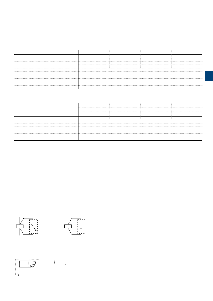
1S
B
C
101
9
0
0
S
0
2
01
ABB
|
3
/63
Surge suppressors for contactor coils
Technical data
Varistor
RV5/50
RV5/133
RV5/250
RV5/440
Rated control circuit voltage Uc
24...50 V AC
50...133 V AC
110...250 V AC
250...440 V AC
24...50 V DC
50...133 V DC
110...250 V DC
250...440 V DC
Residual overvoltage
(clipping voltage)
132 V AC
270 V AC
480 V AC
825 V AC
132 V DC
270 V DC
480 V DC
825 V DC
Opening time growth factor
1.1...1.5
Operating temperature
-20...+70 °C
Connection to the coil terminals
(parallel mounting)
Clip-on for both fixing and connection.
Fixing
Clipped onto the top part of the contactor base without change in contactor overall dimensions.
Advantages
High energy absorption: good damping - Unpolarized system.
Drawback
Clipping as from Uvdr (1), thus voltage front up to this point.
(1) Uvdr = Varistor operating voltage (voltage dependent resistor), tolerance ±10 %.
RC type
RC5-1/50
RC5-1/133
RC5-1/250
RC5-1/440
RC5-2/50
RC5-2/133
RC5-2/250
RC5-2/440
–
–
–
RC5-3/440
Rated control circuit voltage Uc
24...50 V AC
50...133 V AC
110...250 V AC
250...440 V AC
Residual overvoltage
(clipping voltage)
2 to 3 x Uc max.
Opening time growth factor
1.2...1.3
Operating temperature
-20...+70 °C
Connection to the coil terminals
(parallel mounting)
Clip-on for both fixing and connection.
Fixing
Clipped onto the top part of the contactor base without change in contactor overall dimensions.
Advantages
Very fast clipping - Attenuation of steep fronts and thus of high frequencies. No operating delays.
Wiring diagrams
A1
A2
A1
A2
Varistor
RC type
Dimensions
RV5, RC5
The add-on block does not increase the
contactor overall dimensions
3
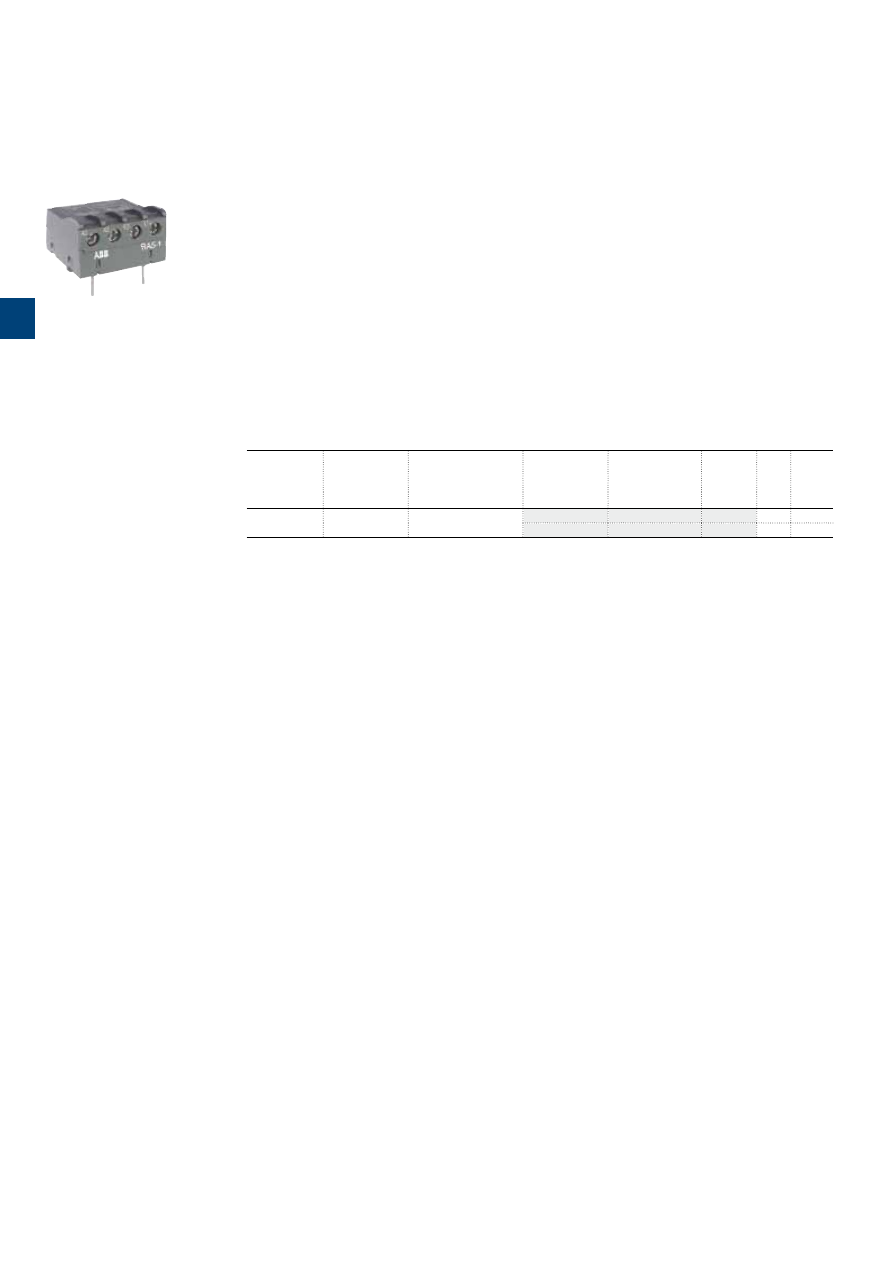
1S
B
C
101
9
01
S
0
2
01
3
/64 |
ABB
Interface relays
Description
RA5-1 interface relay is designed to receive 24 V DC signals delivered by PLC’s or other sources with a
low output power and to restore them with sufficient power to operate the coils of the relevant A9 ... A110
contactors.
RA5-1 interface relay is made up of a miniature electromechanical relay equipped with a N.O. contact and
with a low consumption 24 V DC coil.
The interface relay coil is controlled by the PLC while the N.O. contact ensures switching of the power contactor.
Coil switching gives rise to overvoltages which have adverse effects on the electronic devices, insulators and,
more generally, on component lifetime. The RA5-1 is equipped with surge suppressors:
– on the 24 V DC relay coil via a diode,
– on the power contactor coil via a varistor.
Furthermore, the RA5-1 is protected against relay pole reversal by a diode inserted between the E1 and E2
input terminals.
Ordering details
For contactors
Coil voltages
Rated control circuit
voltage
Uc
Type
Order code
Pkg
qty
Weight
(1 pce)
V 50/60 Hz
V DC
kg
A9 ... A110
24...250
24
RA5-1
1
0.050
RA5-1
10
0.050
1SBC101005F0014
RA5-1
3
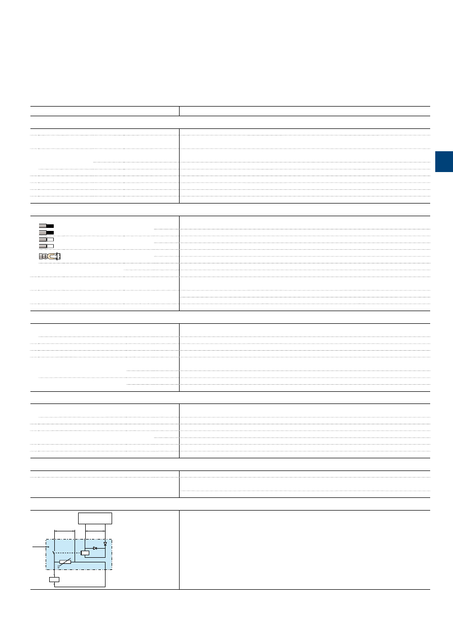
1S
B
C
101
9
0
2S
0
2
01
ABB
|
3
/65
Interface relays
Technical data
Type
RA5-1
Utilization characteristics according to IEC
Standards
IEC 60255-5
Rated insulation voltage Ui
acc. to IEC 60947-4-1
250 V AC
Ambient air temperature
In free air operation
at Uc = 24 V DC (between E1 and E2)
-25…+70 °C
from 0.85 to 1.1 x Uc
-25…+55 °C
Storage
-40…+70 °C
Climatic withstand
Complies with that of associated contactors
Maximum operating altitude
3000 m
Mounting positions
No limitation
Fixing
Using the contactor A1 and A2 teminal connecting parts
Connecting characteristics
Connection capacity
(min. ... max.)
Rigid solid
1 x
1...4 mm²
2 x
1...4 mm²
Flexible with ferrule
1 x
0.75...2.5 mm²
2 x
0.75...2.5 mm²
L
l
Lugs
L <
8 mm
l >
3.5 mm
Tightening torque
Recommended
1 Nm
Max.
1.2 Nm
Degree of protection
acc. to IEC 60947-1 / EN 60947-1 and IEC 60529 / EN 60529
Protection against direct contact in acc. with EN 50274
RA5-1 wired and mounted on the associated contactor
Screw terminals
Delivered in open position, screws of unused terminals must be tightened
All terminals
M3.5
Screwdriver type
Flat Ø 5.5 / Pozidriv 2
Working data
Surge suppression
For contactor coil
Varistor
For interface relay coil
Diode
Protection against polarity reversal between terminals E1 and E2
Diode
Interface relay operating time
Closing and drop-out ≤ 10 ms
Total operating time, interface relay + contactor
Between energization and:
N.O. contact closing
20…37 ms
N.C. contact opening
17…32 ms
Between de-energization and:
N.O. contact opening
17…25 ms
N.C. contact closing
20…28 ms
Electrical input data
Control voltage
(E1 and E2 terminals)
Uc
Rated value
24 V DC
Max. range at ambient temperature 20 °C
19…30 V DC
Max. consumption for Uc = 24 V DC,
θ
= 20 °C
0.3 W
"0" status
(relay open)
for Uc
≤ 2.4 V DC
for Ic
< 1 mA
"1" status
(relay closed)
for Uc
≥ 19 V DC
Max. short supply interruption immunity time
2 ms
Electrical output data
Switching voltage
(A0 and A2 terminals)
≤ 250 V AC
Electrical durability
Number of operating cycles
2 millions (600 cycles/h) on A9 ... A75 contactors or N contactor relays
0.5 million (600 cycles/h) on A95 and A110 contactors
Connection
U
c
≤ 250 V AC
24 V DC
+
–
RA 5-1
A0
E2 –
E1 +
KM1
A1
A2
PLC
Output
A2
The "E1+" and "E2-" input terminals must be connected, according to their polarity, to the PLC output.
The RA5-1 is equipped with two terminal pads for connection to the A1 and the A2 terminals of the
contactor coil.
This coil is supplied between the A0 and the A2 terminals of the RA 5-1.
Mounting: terminals pads clamped inside the contactor coil terminals.
3
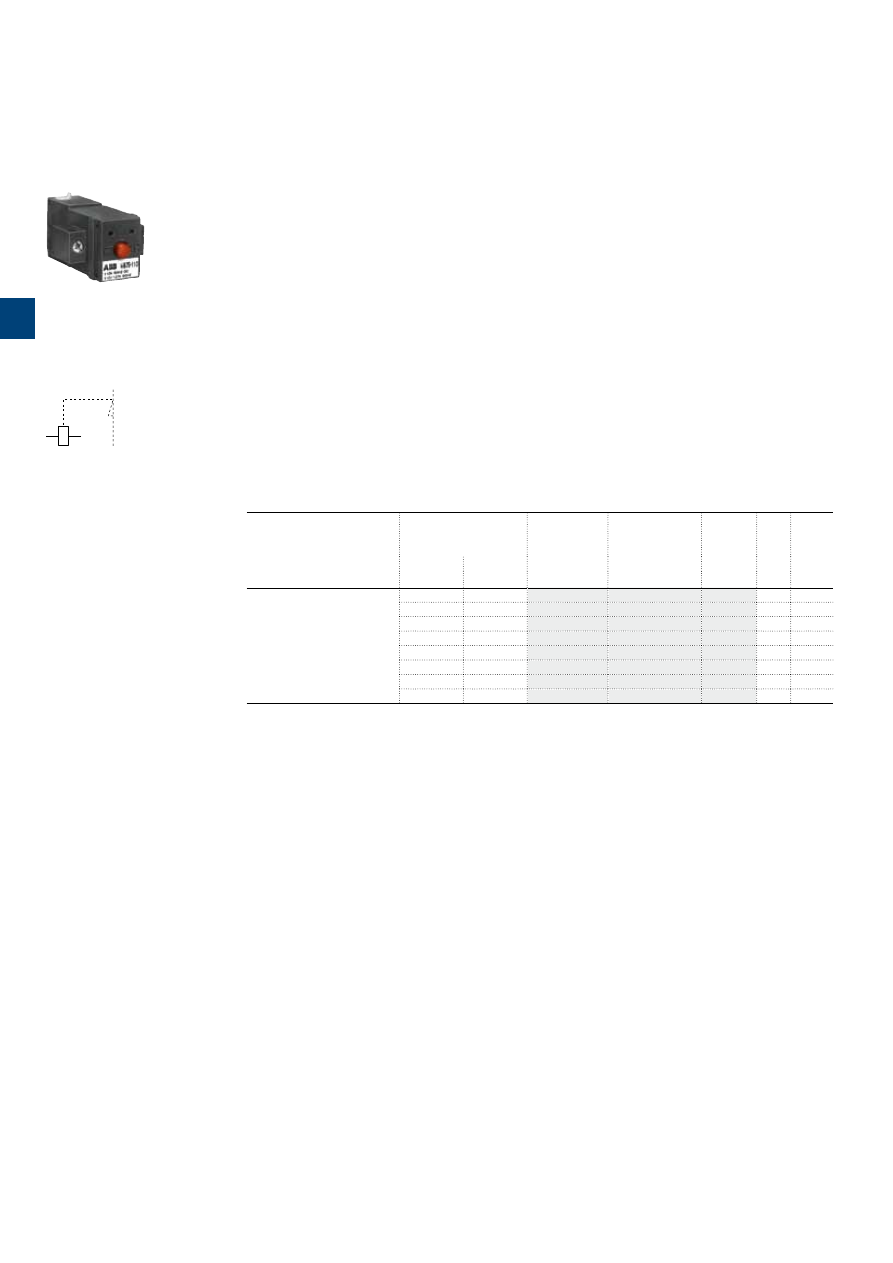
1S
B
C
101
9
0
3
S
0
2
01
3
/66 |
ABB
Mechanical latching units
Description
For converting standard contactors into latched contactors.
The WB75-A block contains a mechanical latching device with electromagnetic impulse unlatching (AC or
DC) or manual unlatching.
Captive screw type connecting terminals, built-in cable clamps, M3.5 (+,-) pozidriv 2 screw with screwdriver
guidance; delivered untightened and protected against accidental direct contact.
Operation
After closing, the contactor continues to be held in the closed position by the latching mechanism should the
supply voltage fail at the contactor coil terminals.
Contactor opening can be controlled:
– electrically by an impulse (AC or DC) on the WB75-A block coil.
(the coil is not designed to be permanently energized)
– manually by pressing the pushbutton on the front face of the WB75-A block.
Mounting
The WB75-A block is clipped onto the front face of the 1-stack contactor where it takes up two slots. The
two other slots may accept CA5... single pole auxiliary contacts (1 block on each side of the mechanical
latch).
Ordering details
For contactors
Rated control circuit
voltage
Uc
Type
Order code
Pkg
qty
Weight
(1 pce)
V 50 Hz
or DC
V 60 Hz
kg
A9 ... A75
24
24...28
WB75-A
1
0.120
42
42...48
WB75-A
1
0.120
48
48...55
WB75-A
1
0.120
110
110...127
WB75-A
1
0.120
220...230
220...255
WB75-A
1
0.120
230...240
230...277
WB75-A
1
0.120
380...415
380...440
WB75-A
1
0.120
415...440
440...480
WB75-A
1
0.120
1SBC565483F0301
WB75-A
E1
E2
Terminal marking
3
1SBC101333S0201 - Rev
. A
ABB
|
3
/67
Mechanical latching units
Technical data
Type
WB75-A
Utilization characteristics according to IEC
Rated insulation voltage Ui
acc. to IEC 60947-1
690 V
Max. electrical impulse time
On AC coil (with load factor 5 %)
20 s
On DC coil (with load factor 3 %)
8 s
Min. electrical impulse time
For latching (energizing of the contactor coil)
AC
50 ms
For pull-out (energizing of the WB block coil)
AC
30 ms
Coil operating limits
AC or DC supply
0.85…1.1 x Uc
AC control voltage
50/60 Hz
Rated control circuit voltage Uc
24…480 V AC
Coil consumption
Average pull-in value
90 VA
Average holding value
60 VA
DC control voltage
Rated control circuit voltage Uc
24…440 V DC
Coil consumption
Average pull-in value
110 W
Average holding value
110 W
Operating time
On contactor closing (latching)
Between coil energization and:
N.O. contact closing
No difference with the operation of a contactor without mechanical latching unit
N.C. contact opening
No difference with the operation of a contactor without mechanical latching unit
On contactor opening (unlatching)
Between WB coil energization and:
N.O. contact opening
5…25 ms
N.C. contact closing
7…28 ms
Mechanical durability
Number of operating cycles
1 million operating cycles
Max. switching frequency
3600 cycles/h with on-load factor of 8 %
Connecting characteristics
Connection capacity
(min. ... max.)
Rigid solid
1 x
1...4 mm²
2 x
1...4 mm²
Flexible with ferrule
1 x
0.75...2.5 mm²
2 x
0.75...2.5 mm²
L
l
Lugs
L <
8 mm
l >
3.5 mm
Tightening torque
Recommended
1 Nm
Max.
1.2 Nm
Screw terminals
Delivered in open position, screws of unused terminals must be tightened
All terminals
M3.5
Screwdriver type
Flat Ø 5.5 / Pozidriv 2
3
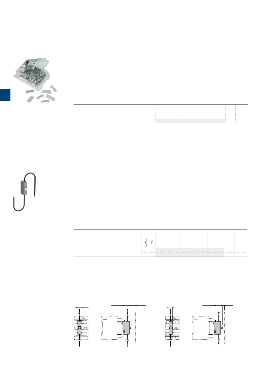
1S
B
C
101
8
9
8
S
0
2
01
3
/68 |
ABB
Function markers
Impulse contact blocks
BA5-50 function markers
Description
Set of 50 function markers designed to be clipped onto the front face of devices. Details can be added to
these markers using a ball point pen, indelible felt-tip pen or pentel white.
Self-adhesive labels (not supplied) can also be added to them.
Marker dimensions: 7 x 19 mm (0.276" x 0.748").
Ordering details
For contactors
Type
Order code
Pkg
qty
Weight
(1 pce)
kg
Contactors, thermal overload relays and accessories
BA5-50
1
0.017
BA5-50
1SBC575874F0301
CB5 impulse contact blocks
Description
Impulse contact blocks are designed for use in enclosures, in association with an adjustable mechanical
pushbutton. Two types are available:
– CB5-10: N.O. contact with a black actuator ("ON" function)
– CB5-01: N.C. contact with a light grey actuator ("OFF" function).
These blocks are equipped with 2 connecting leads 0.5 mm
2
with end, approximately 18 cm long.
Mounting: Clipped onto the front face of the contactors.
Ordering details
For contactors
Contacts Type
Order code
Pkg
qty
Weight
(1 pce)
kg
A9 ... A110
1 –
CB5-10
1
0.012
– 1
CB5-01
1
0.012
Main dimensions
mm,
inches
9.8
0.39"
CB5-10
23.2
0.91"
36
1.42"
10
0.39"
9.8
0.39"
CB5-01
36
1.42"
21.6
0.85"
5
0.2"
CB5
3
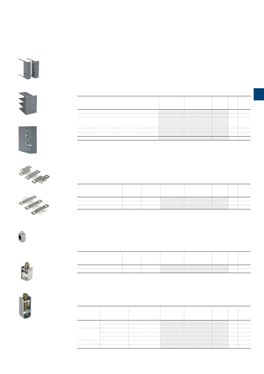
Terminal shrouds, terminal enlargements, terminal extensions
Connector terminals
Terminal shrouds
Description
Main terminal protection for A145 ... A300 contactors.
The auxiliary contact blocks and coils are designed to provide an IP20 degree of protection.
The main terminals, equipped with lugs or connectors, can be protected against accidental direct contact
after wiring (EN 50274) by the addition of terminal shrouds (see table below).
Ordering details
For contactors
Type
Order code
Pkg
qty
Weight
(1 pce)
kg
A145 ... A185 with connectors
LT185-AC
2
0.050
A145 ... A185 with lugs
LT185-AL
2
0.220
A145 ... A185 with short. bar LY185
or between A145 and TA200DU
or between A185 and TA200DU
LT185-AY
1
0.050
A210 ... A300 with connectors
LT300-AC
2
0.070
A210 ... A300 with lugs
LT300-AL
2
0.280
A210 ... A300 with short. bar LY300
LT300-AY
1
0.075
LW... Terminal enlargements
Description
Enlargement pieces designed to increase the width of the contactor terminal pads in order to allow larger
connections to be mounted.
Sets containing 3 tin plated copper bars fixed by an isolating spacer.
Ordering details
For contactors
Dimensions
Type
Order code
Pkg
qty
Weight
(1 pce)
hole Ø
mm
bar
mm
kg
A95, A110
6.5
15 x 3
LW110
1
0.100
A145, A185
10.5
20 x 5
LW185
1
0.250
A210 ... A300
10.5
25 x 5
LW300
1
0.450
LX... Terminal extension
Description
Extension pieces designed to extend the main terminals of contactors for combined mounting of
contactors and connection sets.
Sets containing 3 tin plated copper bars fixed by an isolating spacer.
Ordering details
For contactors
Dimensions
Type
Order code
Pkg
qty
Weight
(1 pce)
hole Ø
mm
bar
mm
kg
A145, A185
8.5
20 x 5
LX185
1
0.250
A210 ... A300
10.5
20 x 5
LX300
1
0.350
Connector terminals
Description
Connection of copper and aluminium cables to the terminal pads of the poles of A contactors.
Ordering details
Cables
For contactors
Cable cross section
Type
Order code
Pkg
qty
Weight
(1 pce)
mm²
kg
Single Cu
A145, A185
6...185
–
3
0.200
A210 ... A300
16...240
–
3
0.400
Single Al & Cu
A145, A185
35...95
–
3
0.100
A145, A185
25...150
–
3
0.100
A210 ... A300
120...240
–
3
0.200
Double Cu
A145, A185
2 x (50...120)
LZ185-2C/120
3
0.300
Double Al & Cu
A210 ... A300
2 x (95...120)
–
3
0.400
1SFT98099-019C3
LT...-AC
1SFT98099-125
LT...-AL
1SFT98000-014
LT...-AY
1SFT98000-011C3
LW...
1SFT98000-012C3
LX...
1SFT98099-00211C1
LZ...
1SFT98099-095C2
LZ...
1SBC580542F0302
LZ...
ABB
|
3
/69
1S
FC
10
115
3
C
0
2
01
3
1S
B
C
101
9
0
4
S
0
2
01
3
/70 |
ABB
Voltage code table
The below tables indicate the available coil voltages and corresponding digits for order codes. When placing an order, please give
the order code. Select a standard contactor from ordering detail pages. Change the
coil voltage code
in the order code accord-
ing to the table below. Example: for contactor A50-30-00 and coil 48 V 50/60 Hz, the order code is 1SBL351001R
Auxiliary contacts
N.O. N.C.
N.O. N.C.
Main contacts
Type
Order code
Contactor type
A40 - 30 - 10
A
AC operated
AC coil code
Contactors: A
AC coil code
Contactors: A
1SBL321001R 80 10
A contactors
50 Hz
60 Hz
81 24 V
24 V
82 42 V
42 V
83 48 V
48 V
84 110 V
110
...120 V
36 190 V
220 V
80
220...
230 V
230
...240 V
88
230...
240 V
240
...260 V
85
380...
400 V
400
...415 V
86
400...
415 V
415
...440 V
50 Hz
60 Hz
81 24 V
24 V
82 42 V
42 V
83 48 V
48 V
84 110 V
110
...120 V
36 190 V
220 V
80
220...
230 V
230
...240 V
88
230...
240 V
240
...260 V
85
380...
400 V
400
...415 V
86
400...
415 V
415
...440 V
Codes in bold for dual frequency coils.
Codes in bold for dual frequency coils.
3
N.O. N.C.
Number contacts
Type
Order code
N 40 E
1SBH141001R 80 40
N contactor relays
Contactor type
AC operated
N

Notes
ABB
|
3
/71
N
4
3
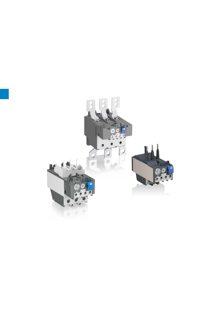
4
/0
| ABB
S
umma
ry
_4
4

Overload relays
ABB
|
4
/1
S
umma
ry
_4
4
Type
TA25DU-M
TA42DU-M
TA75DU-M
TA80DU
TA110DU
TA200DU
TA450DU / TA450SU
Current range
0.10 … 32 A
18 ... 42 A
18 ... 80 A
29 ... 80 A
66 ... 110 A
66 ... 200 A
130 ... 310 A / 40 ... 310 A
Trip class
10A
10A
10A
10A
10A
10A
10A / 30
Single mounting kit
-
DB80
DB80
DB80
DB200
DB200
-
Thermal overload relays
4
/2 |
ABB
4
Type
TA25DU-M
TA42DU-M
TA75DU-M
TA80DU
TA110DU
TA200DU
TA450DU / TA450SU
Current range
0.10 … 32 A
18 ... 42 A
18 ... 80 A
29 ... 80 A
66 ... 110 A
66 ... 200 A
130 ... 310 A / 40 ... 310 A
Trip class
10A
10A
10A
10A
10A
10A
10A / 30
Single mounting kit
-
DB80
DB80
DB80
DB200
DB200
-
ABB
|
4
/3
2C
D
C
10
6
07
0
C
0
2
01
4
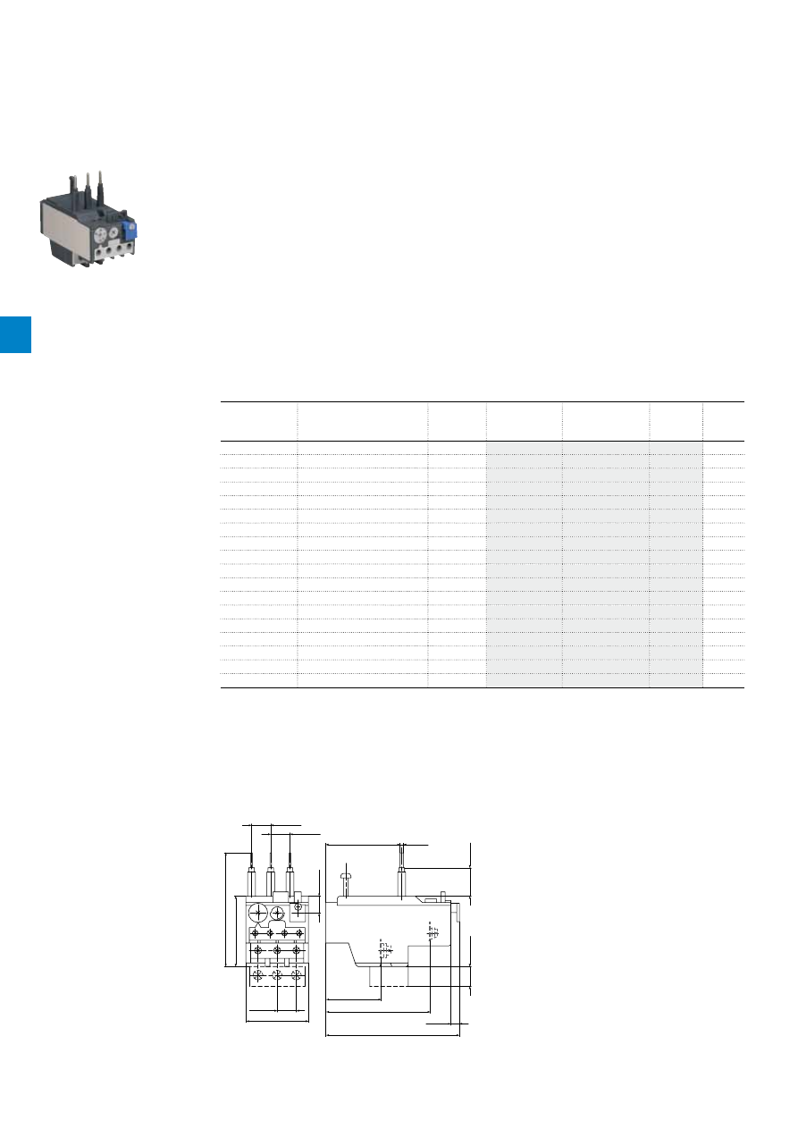
2CDC106056C0201
4
/4 |
ABB
TA25DU-M thermal overload relays
With screw terminals - 0.10 … 32.0 A
Description
The TA25DU-M thermal overload relays are economic electromechanical protection devices for the main
circuit. They offer reliable protection for motors in the event of overload or phase failure. The devices have
trip class 10A.
The thermal overload relays are three pole relays with bimetal tripping elements. The motor current flows
through the bimetal tripping elements and heats them directly and indirectly. In case of an overload (over
current), the bimetal elements bent as a result of the heating. This leads to a release of the relay and a
change of the contacts switching position (95-96 / 97-98).
– Manual or automatic reset selectable
– Phase loss sensitive acc. to IEC/EN 60947-4-1
– Two electrically isolated auxiliary contacts – 1 N.O. + 1 N.C.
– TEST and STOP function – Trip indication on the front
– Temperature compensation
– Suitable for three- and single-phase applications
Ordering details
Setting range
Short-circuit
protective device
Trip class
Type
Order code
Weight
(1 pce)
A
kg
0.10 ... 0.16
0.50 A, Fuse type F
10A
TA25DU-0.16M
0.150
0.16 ... 0.25
0.63 A, Fuse type F
10A
TA25DU-0.25M
0.150
0.25 ... 0.40
1.25 A, Fuse type F
10A
TA25DU-0.4M
0.150
0.40 ... 0.63
2 A, Fuse type gG / -
10A
TA25DU-0.63M
0.150
0.63 ... 1.00
4 A, Fuse type gG / 2 A aM
10A
TA25DU-1.0M
0.150
1.00 ... 1.40
6 A, Fuse type gG / 2 A aM
10A
TA25DU-1.4M
0.150
1.30 ... 1.80
6 A, Fuse type gG / 4 A aM
10A
TA25DU-1.8M
0.150
1.70 ... 2.40
6 A, Fuse type gG / 4 A aM
10A
TA25DU-2.4M
0.150
2.20 ... 3.10
10 A, Fuse type gG / 6 A aM
10A
TA25DU-3.1M
0.150
2.80 ... 4.00
10 A, Fuse type gG / 6 A aM
10A
TA25DU-4.0M
0.150
3.50 ... 5.00
16 A, Fuse type gG / 10 A aM
10A
TA25DU-5.0M
0.150
4.50 ... 6.50
20 A, Fuse type gG / 16 A aM
10A
TA25DU-6.5M
0.150
6.00 ... 8.50
20 A, Fuse type gG / 20 A aM
10A
TA25DU-8.5M
0.150
7.50 ... 11.00
35 A, Fuse type gG / 25 A aM
10A
TA25DU-11M
0.150
10.00 ... 14.00
35 A, Fuse type gG / 25 A aM
10A
TA25DU-14M
0.150
13.00 ... 19.00
50 A, Fuse type gG / 35 A aM
10A
TA25DU-19M
0.170
18.00 ... 25.00
63 A, Fuse type gG / 50 A aM
10A
TA25DU-25M
0.170
24.00 ... 32.00
80 A, Fuse type gG / 63 A aM
10A
TA25DU-32M
0.200
2CDC231019F0013
TA25DU-19M
Main dimensions
mm,
inches
44
1.73"
13.5
0.53"
49.5
1.95"
80
3.15"
13.5
0.53"
13.5
0.53"
12
0.47"
73.5
2.89"
94
3.7"
6
0.24"
20
0.79"
14*
0.55"*
39
1.54"
52.2
2.06"
2.5
0.1"
2CDC232023F0011
TA25DU-M + DX25
4
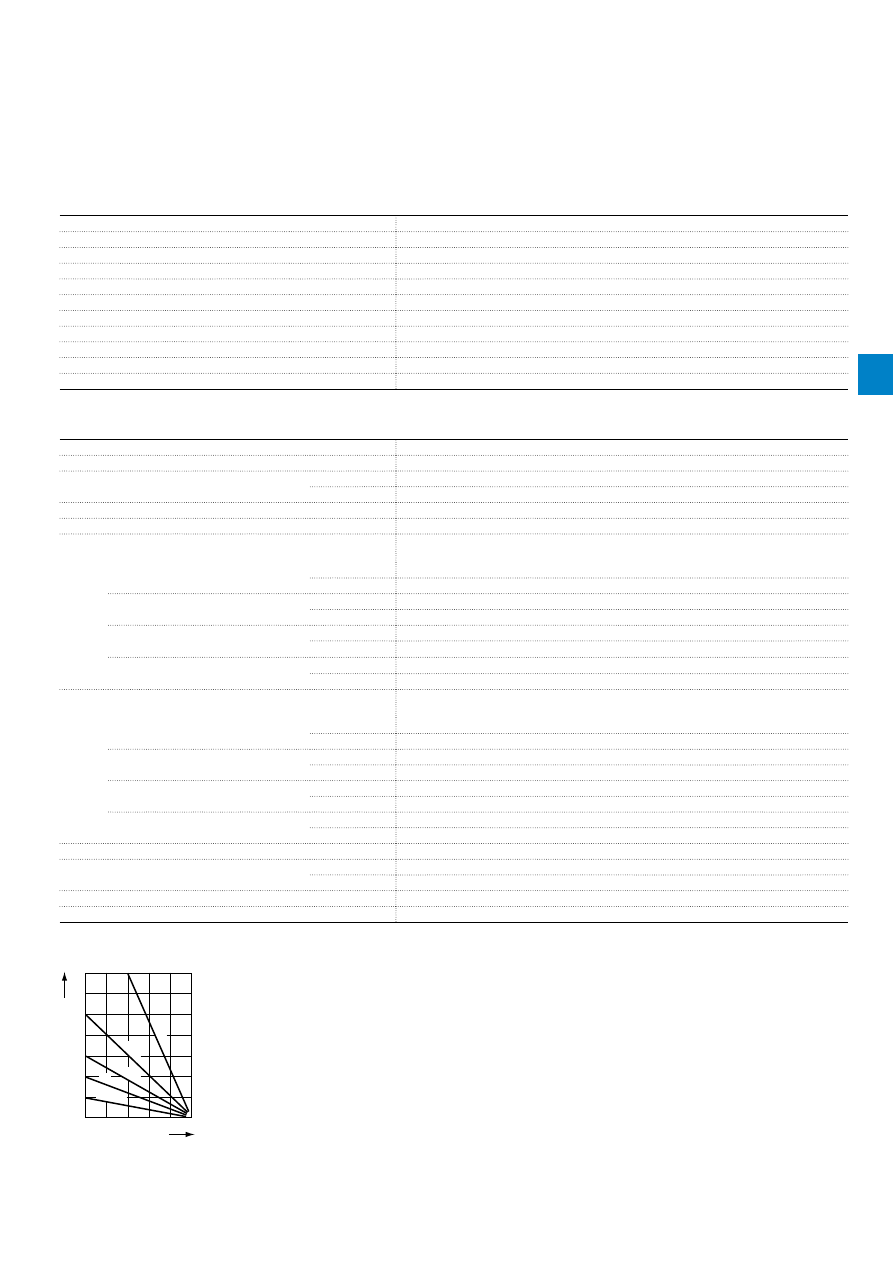
2CDC106056C0201
ABB
|
4
/5
Main circuit – Utilization characteristics according to IEC/EN
Type
TA25DU-M
Standards
IEC/EN 60947–4–1, IEC/EN 60947-5-1, IEC/EN 60947-1
Rated operational voltage U
e
690 V AC
Rated frequency
DC, 50/60 Hz
Frequency range
0 ... 400 Hz
Trip class
10A
Number of poles
3
Duty time
100 %
Operating frequency without early tripping
Up to 15 operations/h, see "Technical diagram – Intermittent periodic duty"
Rated impulse withstand voltage U
imp
6 kV
Rated insulation voltage U
i
690 V AC
Auxiliary circuit according to IEC/EN
Type
TA25DU-M
Rated operational voltage U
e
500 V AC, 440 V DC
Conventional free air thermal current I
th
N.C., 95-96
10 A
N.O., 97-98
6 A
Rated frequency
DC, 50/60 Hz
Number of poles
1 N.O. + 1 N.C.
I
e
/ Rated operational current AC-15
acc. to IEC/EN 60947-5-1 for utilization category
110-120 V
N.C., 95-96
3.00 A
N.O., 97-98
1.50 A
220-230-240 V
N.C., 95-96
3.00 A
N.O., 97-98
1.50 A
440 V
N.C., 95-96
1.00 A
N.O., 97-98
1.00 A
480-500 V
N.C., 95-96
1.00 A
N.O., 97-98
1.00 A
I
e
/ Rated operational current DC-13
acc. to IEC/EN 60947-5-1 for utilization category
24 V
N.C., 95-96
1.25 A
N.O., 97-98
1.25 A
60 V
N.C., 95-96
0.25 A
N.O., 97-98
0.25 A
110-120-125 V
N.C., 95-96
0.25 A
N.O., 97-98
0.25 A
250 V
N.C., 95-96
0.12 A
N.O., 97-98
0.04 A
Minimum switching capacity
17 V / 3 mA
Short-circuit protective device
N.C., 95-96
10 A, Fuse type gG
N.O., 97-98
6 A, Fuse type gG
Rated impulse withstand voltage U
imp
6 kV
Rated insulation voltage U
i
690 V
Technical diagram – Intermittent periodic duty
140
120
0
20
40
60
80
100
0
20
40
60
80 100 (%)
t = 1
s
a
t = 1.5
s
a
t = 3
s
a
t = 5 s
a
t = 0.5
s
a
duty ratio
switching fr
equency
(Op/h)
2CDC232005F0211
t
a
: Motor starting time
TA25DU-M thermal overload relays
Technical data
4
2CDC106056C0201
4
/6 |
ABB
General technical data
Type
TA25DU-M
Pollution degree
3
Phase loss sensitive
Yes
Ambient air temperature
Operation
Open - compensated
-25 ... +55 °C
Open
-25 ... +55 °C
Storage
-40 ... +70 °C
Ambient air temperature compensation
Acc. to IEC/EN60947-4-1
Maximum operating altitude permissible
2000 m
Resistance to shock acc. to IEC 60068-2-27
12g / 15 ms
Mounting position
Position 1-6
Mounting
Mount on the contactor and tighten the screws of the main circuit terminals or with single
mounting kit on DIN rail (35 mm)
Degree of protection
Housing
IP20
Main circuit terminals
IP10
Electrical connection
Main circuit
Type
TA25DU-M
(0.16-11 A)
TA25DU-M
(14-25 A)
TA25DU-M
(32 A)
Connecting capacity
Rigid
1 x
2 x
0.75 ... 4 mm²
0.75 ... 4 mm²
1.5 ... 6 mm²
1.5 ... 6 mm²
1.5 ... 10 mm²
-
Flexible with insulated ferrule
1 x or 2 x
1)
0.75 ... 4 mm²
1.5 ... 4 mm²
1.5 ... 6 mm²
Stripping length
12 mm
12 mm
15 mm
Tightening torques
1.4 - 2.0 Nm
1.4 - 2.0 Nm
2.5 - 3.2 Nm
Connection screw
M4 (Pozidriv 2)
M4 (Pozidriv 2)
M5 (Pozidriv 2)
1)
Combination of different wires not possible
Auxiliary circuit
Type
TA25DU-M
Connecting capacity
Rigid
1 x or 2 x
0.75 ... 4 mm²
Flexible
1 x or 2 x
0.75 ... 2.5 mm²
Stripping length
9 mm
Tightening torques
0.8 ... 1.3 Nm
Connection screw
M3.5 (Pozidriv 2)
TA25DU-M thermal overload relays
Technical data
4
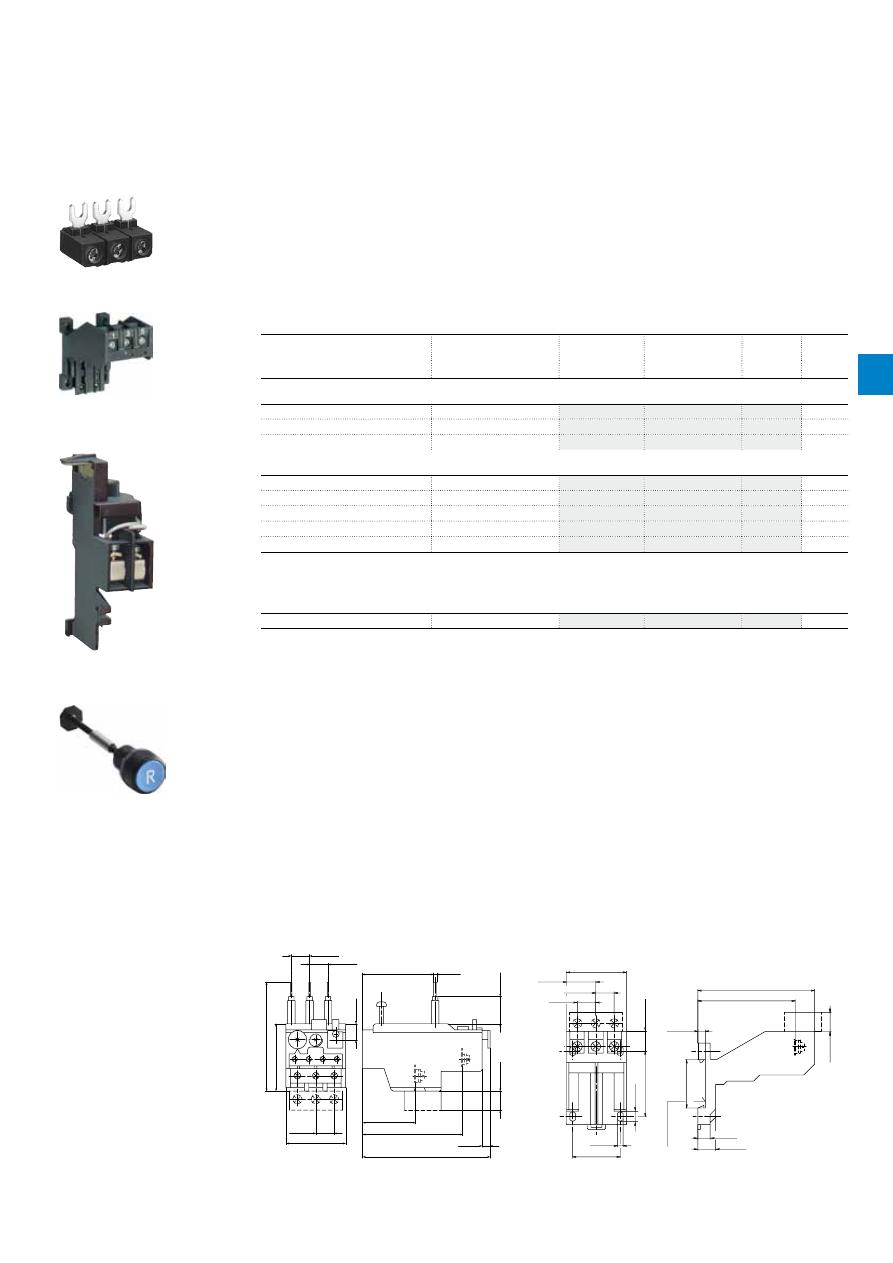
2CDC106056C0201
ABB
|
4
/7
TA25DU-M thermal overload relays
Accessories
Description
The single mounting kits offer the possibility to mount the overload relays separately from the contactor.
The DS25-A allows electrically remote tripping of TA25DU-M. DR25-A coil for remote reset of TA25DU-M.
Ordering details
For thermal overload relays
Description
Type
Order code
Weight
(1 pce)
kg
Terminal block and mounting kits
TA25DU-0.16M; … 25M / DB25/25 A
Terminal block 10 mm²
DX25
0.030
TA25DU-0.16M … 25M
Single mounting kit
DB25/25A
0.055
TA25DU-32M
Single mounting kit
DB25/32A
0.080
Remote reset coil
TA25DU-M
24 V, 50/60 Hz
DR25-A-24
0.050
TA25DU-M
48 V, 50/60 Hz
DR25-A-48
0.050
TA25DU-M
110 V, 50/60 Hz
DR25-A-110
0.050
TA25DU-M
220/380 V, 50/60 Hz
DR25-A-220/380
0.050
TA25DU-M
500 V, 50/60 Hz
DR25-A-500
0.050
The remote reset coil is to be connected to auxiliary contact 97-98 of TA25DU-M.
The coil is not suitable for Continuous operation. Impulse duration: maximum 0.2 seconds.
Accessories for reset function
TA25DU-M
Reset push button*
KPR-101L
0.027
*Note: for more information see catalogue 1SFC151004C0201
SST01494
DX25
2CDC231017F0006
DB25/25A
SST20591
DR25-A-220/380
Main dimensions
mm,
inches
44
1.73"
13.5
0.53"
49.5
1.95"
80
3.15"
13.5
0.53"
13.5
0.53"
12
0.47"
73.5
2.89"
94
3.7"
6
0.24"
20
0.79"
14*
0.55"*
39
1.54"
52.2
2.06"
2.5
0.1"
2CDC232023F0011
4.2
0.17"
35
1.38"
7.5
0.3"
48
1.89"
14*
0.55"
*
85.8
3.38"
71.5
2.81"
5.5
0.22"
35.5
1.4"
9
0.35"
14.5
0.57"
13
0.51"
21.5
0.85"
44
1.73"
13.5
0.53"
13.5
0.53"
DIN rail 35 EN60715
Hutschiene 35 EN60715
2CDC232024F0011
TA25DU-M + DX25
DB25
1SFC151402F0001
KPR-101L
4
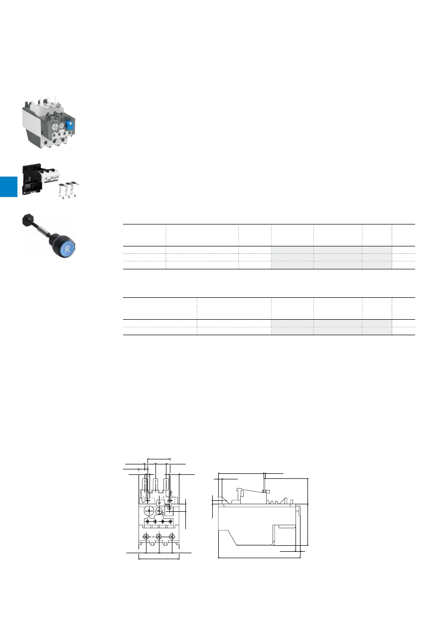
2CDC106057C0201
4
/8 |
ABB
TA42DU-M thermal overload relays
18.0 … 42.0 A
Description
The TA42DU-M thermal overload relays are economic electromechanical protection devices for the main
circuit. They offer reliable protection for motors in the event of overload or phase failure. The devices have
trip class 10A.
The thermal overload relays are three pole relays with bimetal tripping elements. The motor current flows
through the bimetal tripping elements and heats them directly and indirectly. In case of an overload (over
current), the bimetal elements bent as a result of the heating. This leads to a release of the relay and a
change of the contacts switching position (95-96 / 97-98).
– Manual or automatic reset selectable
– Phase loss sensitive acc. to IEC/EN 60947-4-1
– Two electrically isolated auxiliary contacts – 1 N.O. + 1 N.C.
– TEST and STOP function – Trip indication on the front
– Temperature compensation
– Suitable for three- and single-phase applications
Ordering details
Setting range
Short-circuit
protective device
Trip class
Type
Order code
Weight
(1 pce)
A
kg
18 ... 25
63 A, Fuse type gG / 50 A aM
10A
TA42DU-25M
0.335
22 ... 32
80 A, Fuse type gG / 63 A aM
10A
TA42DU-32M
0.335
29 ... 42
100 A, Fuse type gG / 80 A aM
10A
TA42DU-42M
0.335
Ordering details accessories
For thermal overload relays
Description
Type
Order code
Weight
(1 pce)
A
kg
TA42DU-M
Single mounting kit
DB80
0.155
TA42DU-M
Reset push button*
KPR-101L
0.027
*Note: for more information see catalogue 1SFC151004C0201
2CDC231020F0013
TA42DU-32M
2CDC231007F0010
DB80
1SFC151402F0001
KPR-101L
Main dimensions
mm,
inches
10
0.39"
5
0.2"
30
1.18"
14.4
0.57"
14.4
0.57"
7.9
0.3"
0.17"
4.3
13
0.51"
17.5
0.69"
17.5
0.69"
54
2.13"
61.5
2.42"
1.5
0.06"
5
0.2"
34
1.34"
56
2.2"
6
0.24"
110.5
4.35"
2CDC232015F0011
TA42DU-M
4

2CDC106057C0201
ABB
|
4
/9
Main circuit – Utilization characteristics according to IEC/EN
Type
TA42DU-M
Standards
IEC 60947-1 / 60947-4-1 and EN 60947-1 / 60947-4-1
Rated operational voltage U
e
690 V AC
Rated frequency
DC, 50/60 Hz
Trip class
10A
Number of poles
3
Duty time
100 %
Operating frequency without early tripping
Up to 15 operations/h, see "Technical diagram – Intermittent periodic duty"
Rated impulse withstand voltage U
imp
6 kV
Rated insulation voltage U
i
690 V AC
Auxiliary circuit according to IEC/EN
Type
TA42DU-M
Rated operational voltage U
e
500 V AC, 440 V DC
Conventional free air thermal current I
th
N.C., 95-96
10 A
N.O., 97-98
6 A
Rated frequency
DC, 50/60 Hz
Number of poles
1 N.O. + 1 N.C.
I
e
/ Rated operational current AC-15
acc. to IEC/EN 60947-5-1 for utilization category
110-120 V
N.C., 95-96
3.00 A
N.O., 97-98
1.50 A
220-230-240 V
N.C., 95-96
3.00 A
N.O., 97-98
1.50 A
440 V
N.C., 95-96
1.00 A
N.O., 97-98
1.00 A
480-500 V
N.C., 95-96
1.00 A
N.O., 97-98
1.00 A
I
e
/ Rated operational current DC-13
acc. to IEC/EN 60947-5-1 for utilization category
24 V
N.C., 95-96
1.25 A
N.O., 97-98
1.25 A
60 V
N.C., 95-96
0.25 A
N.O., 97-98
0.25 A
110-120-125 V
N.C., 95-96
0.25 A
N.O., 97-98
0.25 A
250 V
N.C., 95-96
0.12 A
N.O., 97-98
0.04 A
Minimum switching capacity
17 V / 3 mA
Short-circuit protective device
N.C., 95-96
10 A, Fuse type gG
N.O., 97-98
6 A, Fuse type gG
Rated impulse withstand voltage U
imp
6 kV
Rated insulation voltage U
i
690 V
Technical diagram – Intermittent periodic duty
140
120
0
20
40
60
80
100
0
20
40
60
80 100 (%)
t = 1
s
a
t = 1.5
s
a
t = 3
s
a
t = 5 s
a
t = 0.5
s
a
duty ratio
switching fr
equency
(Op/h)
2CDC232005F0211
t
a
: Motor starting time
TA42DU-M thermal overload relays
Technical data
4
2CDC106057C0201
4
/10 |
ABB
General technical data
Type
TA42DU-M
Pollution degree
3
Phase loss sensitive
Yes
Ambient air temperature
Operation
Open - compensated
-25 ... +55 °C
Open
-25 ... +55 °C
Storage
-40 ... +70 °C
Ambient air temperature compensation
Acc. to IEC/EN60947-4-1
Maximum operating altitude permissible
2000 m
Resistance to shock acc. to IEC 60068-2-27
12g / 15 ms
Mounting position
Position 1-6
Mounting
Mount on the contactor and tighten the screws of the main circuit terminals or with single
mounting kit on DIN rail (35 mm)
Degree of protection
Housing
IP20
Main circuit terminals
IP10
Electrical connection
Main circuit
Type
TA42DU-M
Connecting capacity
Rigid
1 x
2 x
2.5 ... 25 mm²
2.5 ... 16 mm²
Flexible with insulated ferrule
1 x
2 x
2.5 ... 25 mm²
2.5 ... 10 mm²
Stripping length
14 mm
Tightening torques
4.5 Nm
Connection screw
M6 (Pozidriv 2)
Auxiliary circuit
Type
TA42DU-M
Connecting capacity
Rigid
1 x or 2 x
0.75 ... 4 mm²
Flexible with ferrule
1 x or 2 x
0.75 ... 2.5 mm²
Flexible with insulated ferrule
1 x or 2 x
0.75 ... 2.5 mm²
Flexible
1 x or 2 x
0.75 ... 2.5 mm²
Stripping length
9 mm
Tightening torques
0.8 ... 1.3 Nm
Connection screw
M3.5 (Pozidriv 2)
TA42DU-M thermal overload relays
Technical data
4
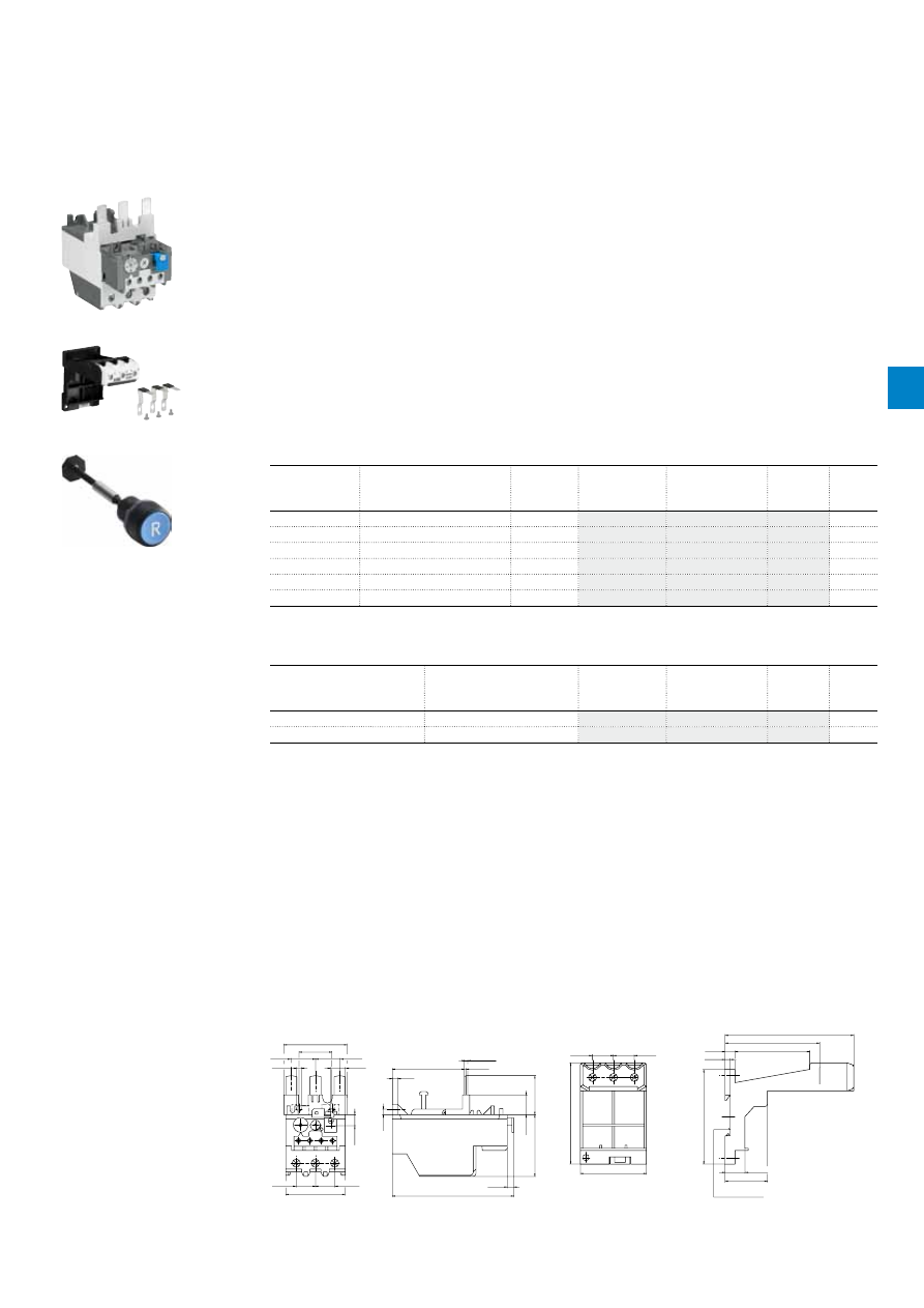
2CDC106058C0201
ABB
|
4
/11
TA75DU-M thermal overload relays
18 … 80 A
Description
The TA75DU-M thermal overload relays are economic electromechanical protection devices for the main
circuit. They offer reliable protection for motors in the event of overload or phase failure. The devices have
trip class 10A.
The thermal overload relays are three pole relays with bimetal tripping elements. The motor current flows
through the bimetal tripping elements and heats them directly and indirectly. In case of an overload (over
current), the bimetal elements bent as a result of the heating. This leads to a release of the relay and a
change of the contacts switching position (95-96 / 97-98).
– Manual or automatic reset selectable
– Phase loss sensitive acc. to IEC/EN 60947-4-1
– Two electrically isolated auxiliary contacts – 1 N.O. + 1 N.C.
– TEST and STOP function – Trip indication on the front
– Temperature compensation
– Suitable for three- and single-phase applications
Ordering details
Setting range
Short-circuit
protective device
Trip class
Type
Order code
Weight
(1 pce)
A
kg
18 ... 25
63 A, Fuse type gG / 50 A aM
10A
TA75DU-25M
0.335
22 ... 32
80 A, Fuse type gG / 63 A aM
10A
TA75DU-32M
0.335
29 ... 42
100 A, Fuse type gG / 80 A aM
10A
TA75DU-42M
0.335
36 ... 52
125 A, Fuse type gG / 100 A aM 10A
TA75DU-52M
0.335
45 ... 63
160 A, Fuse type gG / 125 A aM 10A
TA75DU-63M
0.335
60 ... 80
200 A, Fuse type gG / 160 A aM 10A
TA75DU-80M
0.370
Ordering details accessories
For thermal overload relays
Description
Type
Order code
Weight
(1 pce)
A
kg
TA75DU-M
Single mounting kit
DB80
0.155
TA75DU-M
Reset push button*
KPR-101L
0.027
*Note: for more information see catalogue 1SFC151004C0201
2CDC231022F0013
TA75DU-63M
2CDC231007F0010
DB80
1SFC151402F0001
KPR-101L
Main dimensions
mm,
inches
30
1.18"
22
0.87"
57.5
2.26"
22
0.87"
13
0.51"
4.3
0.17"
67(65.5*)
2.64"(2.58")
10
0.39"
5
0.2"
5
0.2"
17.5
0.69"
17.5
0.69"
54
2.13"
6
0.24"
110.5
4.35"
18
0.71"
56
2.2"
35.5
1.4"
1.5
0.06"
(3*)
(0.12"*)
2CDC232017F0011
19
0.75"
19
0.75"
92
3.62"
60
2.36"
4.7
0.19"
9
0.35"
68
2.68"
86
3.39"
117
4.61"
86
3.39"
38.5
1.52"
18
0.71"
DIN rail 35 EN60715
Hutschiene 35 EN60715
2CDC232025F0011
TA75DU-M
DB80
4
2CDC106058C0201
4
/12 |
ABB
Main circuit – Utilization characteristics according to IEC/EN
Type
TA75DU-M
Standards
IEC 60947-1 / 60947-4-1 and EN 60947-1 / 60947-4-1
Rated operational voltage U
e
690 V AC
Rated frequency
DC, 50/60 Hz
Trip class
10A
Number of poles
3
Duty time
100 %
Operating frequency without early tripping
Up to 15 operations/h, see "Technical diagram – Intermittent periodic duty"
Rated impulse withstand voltage U
imp
6 kV
Rated insulation voltage U
i
690 V AC
Auxiliary circuit according to IEC/EN
Type
TA75DU-M
Rated operational voltage U
e
500 V AC, 440 V DC
Conventional free air thermal current I
th
N.C., 95-96
10 A
N.O., 97-98
6 A
Rated frequency
DC, 50/60 Hz
Number of poles
1 N.O. + 1 N.C.
I
e
/ Rated operational current AC-15
acc. to IEC/EN 60947-5-1 for utilization category
110-120 V
N.C., 95-96
3.00 A
N.O., 97-98
1.50 A
220-230-240 V
N.C., 95-96
3.00 A
N.O., 97-98
1.50 A
440 V
N.C., 95-96
1.00 A
N.O., 97-98
1.00 A
480-500 V
N.C., 95-96
1.00 A
N.O., 97-98
1.00 A
I
e
/ Rated operational current DC-13
acc. to IEC/EN 60947-5-1 for utilization category
24 V
N.C., 95-96
1.25 A
N.O., 97-98
1.25 A
60 V
N.C., 95-96
0.25 A
N.O., 97-98
0.25 A
110-120-125 V
N.C., 95-96
0.25 A
N.O., 97-98
0.25 A
250 V
N.C., 95-96
0.12 A
N.O., 97-98
0.04 A
Minimum switching capacity
17 V / 3 mA
Short-circuit protective device
N.C., 95-96
10 A, Fuse type gG
N.O., 97-98
6 A, Fuse type gG
Rated impulse withstand voltage U
imp
6 kV
Rated insulation voltage U
i
690 V
Technical diagram – Intermittent periodic duty
140
120
0
20
40
60
80
100
0
20
40
60
80 100 (%)
t = 1
s
a
t = 1.5
s
a
t = 3
s
a
t = 5 s
a
t = 0.5
s
a
duty ratio
switching fr
equency
(Op/h)
2CDC232005F0211
t
a
: Motor starting time
TA75DU-M thermal overload relays
Technical data
4
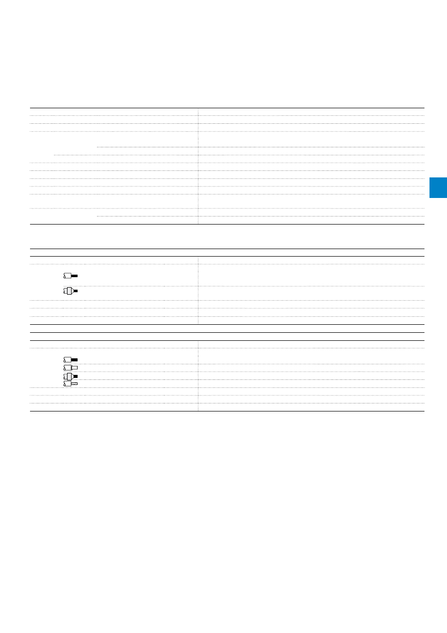
2CDC106058C0201
ABB
|
4
/13
General technical data
Type
TA75DU-M
Pollution degree
3
Phase loss sensitive
Yes
Ambient air temperature
Operation
Open - compensated
-25 ... +55 °C
Open
-25 ... +55 °C
Storage
-40 ... +70 °C
Ambient air temperature compensation
Acc. to IEC/EN60947-4-1
Maximum operating altitude permissible
2000 m
Resistance to shock acc. to IEC 60068-2-27
12g / 15 ms
Mounting position
Position 1-6
Mounting
Mount on the contactor and tighten the screws of the main circuit terminals or with single
mounting kit on DIN rail (35 mm)
Degree of protection
Housing
IP20
Main circuit terminals
IP10
Electrical connection
Main circuit
Type
TA75DU-M
Connecting capacity
Rigid
1 x
2 x
2.5 ... 25 mm²
2.5 ... 16 mm²
Flexible with insulated ferrule
1 x
2 x
2.5 ... 25 mm²
2.5 ... 10 mm²
Stripping length
14 mm
Tightening torques
4.5 Nm
Connection screw
M6 (Pozidriv 2)
Auxiliary circuit
Type
TA75DU-M
Connecting capacity
Rigid
1 x or 2 x
0.75 ... 4 mm²
Flexible with ferrule
1 x or 2 x
0.75 ... 2.5 mm²
Flexible with insulated ferrule
1 x or 2 x
0.75 ... 2.5 mm²
Flexible
1 x or 2 x
0.75 ... 2.5 mm²
Stripping length
9 mm
Tightening torques
0.8 ... 1.3 Nm
Connection screw
M3.5 (Pozidriv 2)
TA75DU-M thermal overload relays
Technical data
4
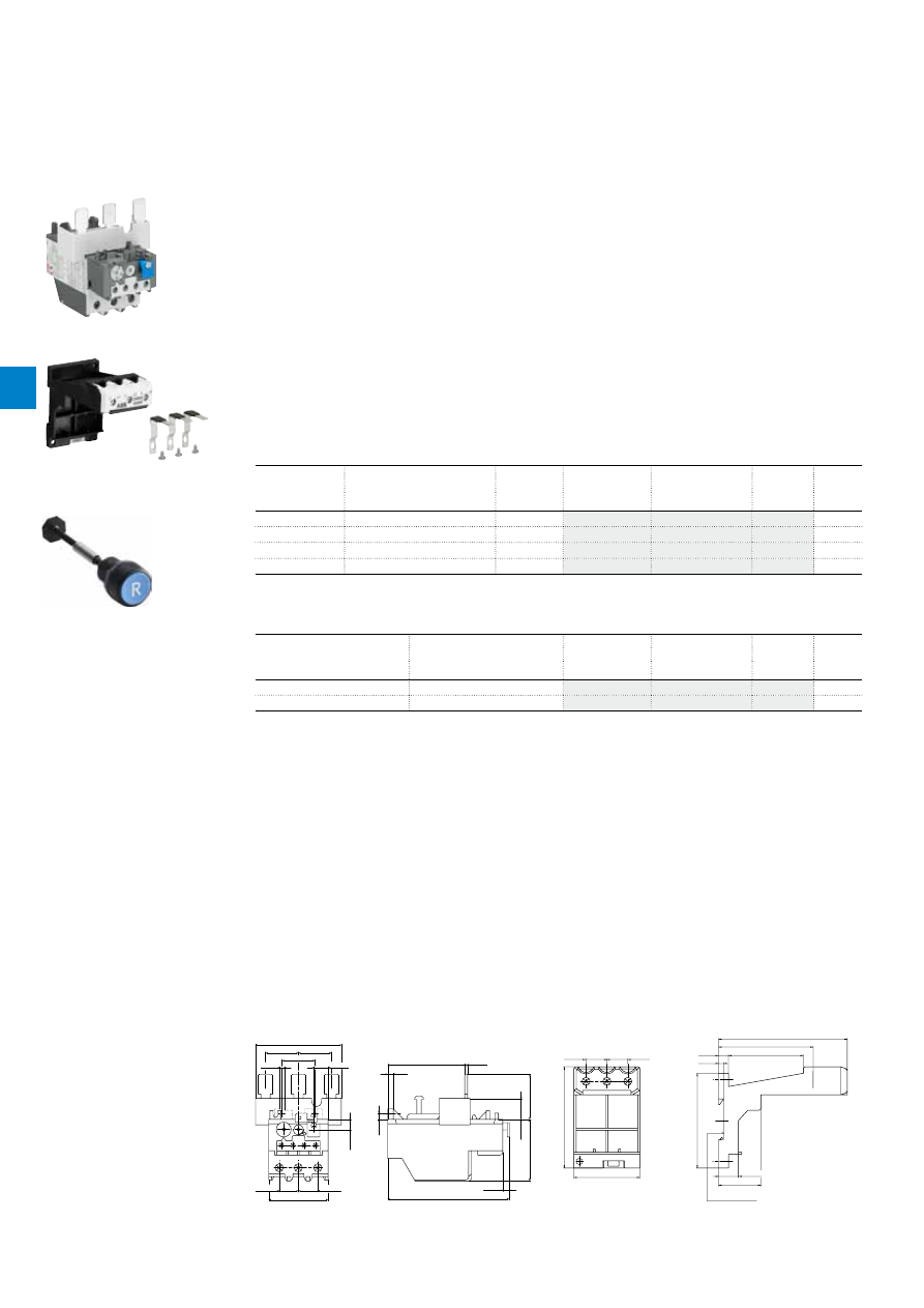
2CDC106044C0201
4
/14 |
ABB
TA80DU thermal overload relays
29 … 80 A
Description
The TA80DU thermal overload relays are economic electromechanical protection devices for the main
circuit. They offer reliable protection for motors in the event of overload or phase failure. The devices have
trip class 10A.
The thermal overload relays are three pole relays with bimetal tripping elements. The motor current flows
through the bimetal tripping elements and heats them directly and indirectly. In case of an overload (over
current), the bimetal elements bent as a result of the heating. This leads to a release of the relay and a
change of the contacts switching position (95-96 / 97-98).
– Manual or automatic reset selectable
– Phase loss sensitive acc. to IEC/EN 60947-4-1
– Two electrically isolated auxiliary contacts – 1 N.O. + 1 N.C.
– TEST and STOP function – Trip indication on the front
– Temperature compensation
– Suitable for three- and single-phase applications
Ordering details
Setting range
Short-circuit
protective device
Trip class
Type
Order code
Weight
(1 pce)
A
kg
29 ... 42
100 A, Fuse type gG / 80 A aM
10A
TA80DU-42
0.360
36 ... 52
125 A, Fuse type gG / 100 A aM 10A
TA80DU-52
0.365
45 ... 63
160 A, Fuse type gG / 125 A aM 10A
TA80DU-63
0.365
60 ... 80
200 A, Fuse type gG / 160 A aM 10A
TA80DU-80
0.375
Ordering details accessories
For thermal overload relay
Description
Type
Order code
Weight
(1 pce)
A
kg
TA80DU
Single mounting kit
DB80
0.155
TA80DU
Reset push button*
KPR-101L
0.027
*Note: for more information see catalogue 1SFC151004C0201
2CDC231008F0011
TA80DU-80
2CDC231007S0010
DB80
Main dimensions
mm,
inches
19
0.75"
56
2.2"
41
1.61"
6
0.24"
110.5
4.35"
10
0.39"
5
0.2"
70
2.76"
2.5
0.1"
5
0.2"
78
3.07"
17.5
0.69"
17.5
0.69"
54
2.13"
30
1.18"
30
1.18"
13
0.51"
4.3
0.17"
30
1.18"
2CDC232018F0011
19
0.75"
19
0.75"
92
3.62"
60
2.36"
4.7
0.19"
9
0.35"
68
2.68"
86
3.39"
117
4.61"
86
3.39"
38.5
1.52"
18
0.71"
DIN rail 35 EN60715
Hutschiene 35 EN60715
2CDC232025F0011
TA80DU
DB80
1SFC151402F0001
KPR-101L
4

2CDC106044C0201
ABB
|
4
/15
Main circuit – Utilization characteristics according to IEC/EN
Type
TA80DU
Standards
IEC 60947-1 / 60947-4-1 and EN 60947-1 / 60947-4-1
Rated operational voltage U
e
690 V AC
Rated frequency
DC, 50/60 Hz
Frequency range
0 ... 400 Hz
Trip class
10A
Number of poles
3
Duty time
100 %
Operating frequency without early tripping
Up to 15 operations/h, see "Technical diagram – Intermittent periodic duty"
Rated impulse withstand voltage U
imp
6 kV
Rated insulation voltage U
i
690 V AC
Auxiliary circuit according to IEC/EN
Type
TA80DU
Rated operational voltage U
e
500 V AC, 440 V DC
Conventional free air thermal current I
th
N.C., 95-96
10 A
N.O., 97-98
6 A
Rated frequency
DC, 50/60 Hz
Number of poles
1 N.O. + 1 N.C.
I
e
/ Rated operational current AC-15
acc. to IEC/EN 60947-5-1 for utilization category
110-120 V
N.C., 95-96
3.00 A
N.O., 97-98
1.50 A
220-230-240 V
N.C., 95-96
3.00 A
N.O., 97-98
1.50 A
440 V
N.C., 95-96
1.00 A
N.O., 97-98
1.00 A
480-500 V
N.C., 95-96
1.00 A
N.O., 97-98
1.00 A
I
e
/ Rated operational current DC-13
acc. to IEC/EN 60947-5-1 for utilization category
24 V
N.C., 95-96
1.25 A
N.O., 97-98
1.25 A
60 V
N.C., 95-96
0.25 A
N.O., 97-98
0.25 A
110-120-125 V
N.C., 95-96
0.25 A
N.O., 97-98
0.25 A
250 V
N.C., 95-96
0.12 A
N.O., 97-98
0.04 A
Minimum switching capacity
17 V / 3 mA
Short-circuit protective device
N.C., 95-96
10 A, Fuse type gG
N.O., 97-98
6 A, Fuse type gG
Rated impulse withstand voltage U
imp
6 kV
Rated insulation voltage U
i
690 V
Technical diagram – Intermittent periodic duty
140
120
0
20
40
60
80
100
0
20
40
60
80 100 (%)
t = 1
s
a
t = 1.5
s
a
t = 3
s
a
t = 5 s
a
t = 0.5
s
a
duty ratio
switching fr
equency
(Op/h)
2CDC232005F0211
t
a
: Motor starting time
TA80DU thermal overload relays
Technical data
4
2CDC106044C0201
4
/16 |
ABB
Main circuit – Utilization characteristics according to UL/CSA
Type
TA80DU
Standards
UL 508, CSA 22.2 No. 14
Maximum operational voltage
600 V AC
Trip rating
125 % of FLA
Full load amps (FLA)
See table "Full load amps and short-circuit protective device"
Short-circuit rating RMS symmetrical
See table "Full load amps and short-circuit protective device"
Short-circuit protective device
See table "Full load amps and short-circuit protective device"
Auxiliary circuit according to UL/CSA
Type
TA80DU
Contact rating
N.C., 95-96
C600
N.O., 97-98
B600
Conventional thermal current
5 A
Full load amps and short-circuit protective device
Type
Full load amps (FLA)
Short-circuit protective device
480 / 600 V AC
Short circuit rating RMS symmetrical Fuse type
Listed circuit breaker
TA80DU-42
42 A
5 kA
150 A, K5 / RK5
80 A
TA80DU-52
52 A
5 kA
175 A, K5 / RK5
125 A
TA80DU-63
63 A
10 kA
200 A, K5 / RK5
125 A
TA80DU-80
80 A
10 kA
250 A, K5 / RK5
125 A
TA80DU thermal overload relays
Technical data
4

2CDC106044C0201
ABB
|
4
/17
General technical data
Type
TA80DU
Pollution degree
3
Phase loss sensitive
Yes
Ambient air temperature
Operation
Open - compensated
-25 ... +55 °C
Open
-25 ... +55 °C
Storage
-40 ... +70 °C
Ambient air temperature compensation
Acc. to IEC/EN60947-4-1
Maximum operating altitude permissible
2000 m
Resistance to shock acc. to IEC 60068-2-27
12g / 15 ms
Mounting position
Position 1-6
Mounting
Mount on the contactor and tighten the screws of the main circuit terminals or with single
mounting kit on DIN rail (35 mm)
Degree of protection
Housing
IP20
Main circuit terminals
IP10
Electrical connection
Main circuit
Type
TA80DU
Connecting capacity
Rigid
1 x
2 x
2.5 ... 25 mm²
2.5 ... 16 mm²
Flexible with insulated ferrule
1 x
2 x
2.5 ... 25 mm²
2.5 ... 10 mm²
Stranded acc. to UL/CSA
1 x or 2 x
AWG 8-1
Flexible acc. to UL/CSA
1 x or 2 x
AWG 8-1
Stripping length
14 mm
Tightening torques
4.5 Nm / 40 Ib.in
Connection screw
M6 (Pozidriv 2)
Auxiliary circuit
Type
TA80DU
Connecting capacity
Rigid
1 x or 2 x
0.75 ... 4 mm²
Flexible with ferrule
1 x or 2 x
0.75 ... 2.5 mm²
Flexible with insulated ferrule
1 x or 2 x
0.75 ... 2.5 mm²
Flexible
1 x or 2 x
0.75 ... 2.5 mm²
Stranded acc. to UL/CSA
1 x or 2 x
AWG 18-14
Flexible acc. to UL/CSA
1 x or 2 x
AWG 18-14
Stripping length
9 mm
Tightening torques
0.8 ... 1.3 Nm / 12 Ib.in
Connection screw
M3.5 (Pozidriv 2)
TA80DU thermal overload relays
Technical data
4
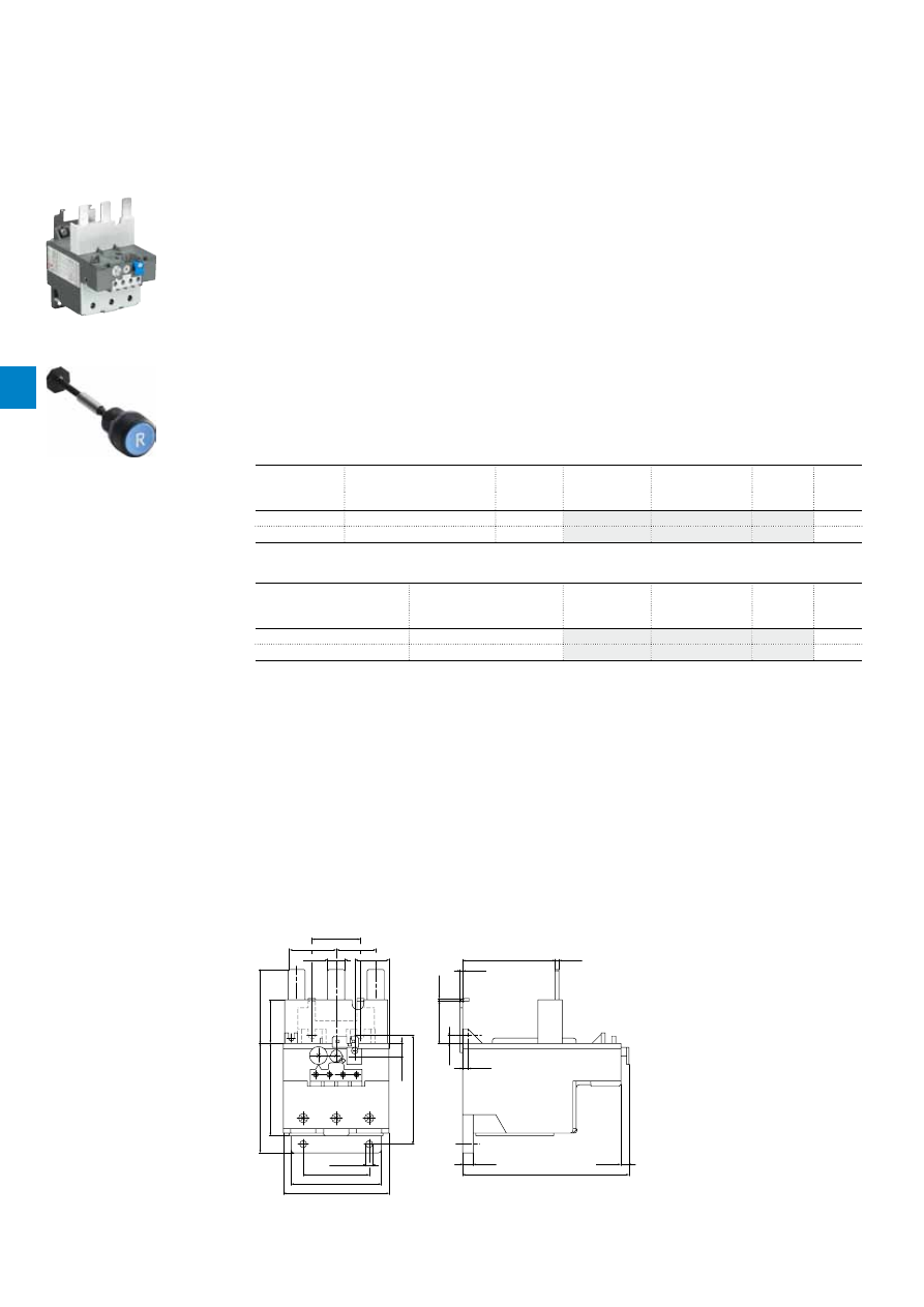
2CDC106037C0201
4
/18 |
ABB
TA110DU thermal overload relays
66 … 110 A
Description
The TA110DU thermal overload relays are economic electromechanical protection devices for the main
circuit. They offer reliable protection for motors in the event of overload or phase failure. The devices have
trip class 10A.
The thermal overload relays are three pole relays with bimetal tripping elements. The motor current flows
through the bimetal tripping elements and heats them directly and indirectly. In case of an overload (over
current), the bimetal elements bent as a result of the heating. This leads to a release of the relay and a
change of the contacts switching position (95-96 / 97-98).
– Manual or automatic reset selectable
– Phase loss sensitive acc. to IEC/EN 60947-4-1
– Two electrically isolated auxiliary contacts – 1 N.O. + 1 N.C.
– TEST and STOP function – Trip indication on the front
– Temperature compensation
– Suitable for three- and single-phase applications
Ordering details
Setting range
Short-circuit
protective device
Trip class
Type
Order code
Weight
(1 pce)
A
kg
66 ... 90
200 A, Fuse type gG / 160 A aM 10A
TA110DU-90
0.750
80 ... 110
224 A, Fuse type gG / 200 A aM 10A
TA110DU-110
0.755
Ordering details accessories
For thermal overload relays
Description
Type
Order code
Weight
(1 pce)
A
kg
TA110DU
Single mounting kit
DB200
0.225
TA110DU
Reset push button*
KPR-101L
0.027
*Note: for more information see catalogue 1SFC151004C0201
2CDC231009F0011
TA110DU-110
Main dimensions
mm,
inches
8
0.31"
126
4.96"
6
0.24"
6
0.24"
32
1.26"
10
0.39"
82.3
3.24"
4
0.16"
70
2.76"
3
0.12"
2
0.08"
2
0.08"
13
0.51"
26
1.02"
37
1.46"
30
1.18"
30
1.4"
70
2.76"
33
1.3"
83
3.27"
56
2.2"
Ø 5.3
Ø 0.21"
50
1.97"
68
2.68"
80
3.15"
2CDC232020F0011
TA110DU
1SFC151402F0001
KPR-101L
4

2CDC106037C0201
ABB
|
4
/19
Main circuit – Utilization characteristics according to IEC/EN
Type
TA110DU
Standards
IEC 60947-1 / 60947-4-1 and EN 60947-1 / 60947-4-1
Rated operational voltage U
e
690 V AC
Rated frequency
DC, 50/60 Hz
Frequency range
0 ... 400 Hz
Trip class
10A
Number of poles
3
Duty time
100 %
Operating frequency without early tripping
Up to 15 operations/h, see "Technical diagram – Intermittent periodic duty"
Rated impulse withstand voltage U
imp
6 kV
Rated insulation voltage U
i
690 V AC
Auxiliary circuit according to IEC/EN
Type
TA110DU
Rated operational voltage U
e
500 V AC, 440 V DC
Conventional free air thermal current I
th
N.C., 95-96
10 A
N.O., 97-98
6 A
Rated frequency
DC, 50/60 Hz
Number of poles
1 N.O. + 1 N.C.
I
e
/ Rated operational current AC-15
acc. to IEC/EN 60947-5-1 for utilization category
110-120 V
N.C., 95-96
3.00 A
N.O., 97-98
1.50 A
220-230-240 V
N.C., 95-96
3.00 A
N.O., 97-98
1.50 A
440 V
N.C., 95-96
1.00 A
N.O., 97-98
1.00 A
480-500 V
N.C., 95-96
1.00 A
N.O., 97-98
1.00 A
I
e
/ Rated operational current DC-13
acc. to IEC/EN 60947-5-1 for utilization category
24 V
N.C., 95-96
1.25 A
N.O., 97-98
1.25 A
60 V
N.C., 95-96
0.25 A
N.O., 97-98
0.25 A
110-120-125 V
N.C., 95-96
0.25 A
N.O., 97-98
0.25 A
250 V
N.C., 95-96
0.12 A
N.O., 97-98
0.04 A
Minimum switching capacity
17 V / 3 mA
Short-circuit protective device
N.C., 95-96
10 A, Fuse type gG
N.O., 97-98
6 A, Fuse type gG
Rated impulse withstand voltage U
imp
6 kV
Rated insulation voltage U
i
690 V
Technical diagram – Intermittent periodic duty
140
120
0
20
40
60
80
100
0
20
40
60
80 100 (%)
t = 1
s
a
t = 1.5
s
a
t = 3
s
a
t = 5 s
a
t = 0.5
s
a
duty ratio
switching fr
equency
(Op/h)
2CDC232005F0211
t
a
: Motor starting time
TA110DU thermal overload relays
Technical data
4

2CDC106037C0201
4
/20 |
ABB
Main circuit – Utilization characteristics according to UL/CSA
Type
TA110DU
Standards
UL 508, CSA 22.2 No. 14
Maximum operational voltage
600 V AC
Trip rating
125 % of FLA
Full load amps (FLA)
See table "Full load amps and short-circuit protective device"
Short-circuit rating RMS symmetrical
See table "Full load amps and short-circuit protective device"
Short-circuit protective device
See table "Full load amps and short-circuit protective device"
Auxiliary circuit according to UL/CSA
Type
TA110DU
Contact rating
N.C., 95-96
C600
N.O., 97-98
B600
Conventional thermal current
5 A
Full load amps and short-circuit protective device
Type
Full load amps
(FLA)
Short-circuit protective device
480 / 600 V AC
Short circuit rating
RMS symmetrical
Fuse type
Listed circuit
breaker
Short circuit rating
RMS symmetrical
Fuse type
Short circuit rating
RMS symmetrical
Listed circuit
breaker
TA110DU-90
90 A
10 kA
250 A, K5 / RK5 150 A
65 kA
200 A, Class J
65 / 25 kA
150 A
TA110DU-110
110 A
10 kA
250 A, K5 / RK5 250 A
65 kA
200 A, Class J
65 / 25 kA
150 A
TA110DU thermal overload relays
Technical data
4
2CDC106037C0201
ABB
|
4
/21
General technical data
Type
TA110DU
Pollution degree
3
Phase loss sensitive
Yes
Ambient air temperature
Operation
Open - compensated
-25 ... +55 °C
Open
-25 ... +55 °C
Storage
-40 ... +70 °C
Ambient air temperature compensation
Acc. to IEC/EN60947-4-1
Maximum operating altitude permissible
2000 m
Resistance to shock acc. to IEC 60068-2-27
12g / 15 ms
Mounting position
Position 1-6
Mounting
Mount on the contactor and tighten the screws of the main circuit terminals or with single
mounting kit
Degree of protection
Housing
IP20
Main circuit terminals
IP10
Electrical connection
Main circuit
Type
TA110DU
Connecting capacity
Rigid
1 x
2 x
16 ... 35 mm²
-
Flexible
1 x
2 x
16 ... 35 mm²
-
Stranded acc. to UL/CSA
1 x or 2 x
AWG 6-2/0
Flexible acc. to UL/CSA
1 x or 2 x
AWG 6-2/0
Stripping length
25 mm
Tightening torques
7.2 ... 9.6 Nm / 40 Ib.in
Connection screw
M8 (Hexagon)
Auxiliary circuit
Type
TA110DU
Connecting capacity
Rigid
1 x or 2 x
0.75 ... 4 mm²
Flexible with ferrule
1 x or 2 x
0.75 ... 2.5 mm²
Flexible with insulated ferrule
1 x or 2 x
0.75 ... 2.5 mm²
Flexible
1 x or 2 x
0.75 ... 2.5 mm²
Stranded acc. to UL/CSA
1 x or 2 x
AWG 18-14
Flexible acc. to UL/CSA
1 x or 2 x
AWG 18-14
Stripping length
9 mm
Tightening torques
0.8 ... 1.3 Nm / 12 Ib.in
Connection screw
M3.5 (Pozidriv 2)
TA110DU thermal overload relays
Technical data
4
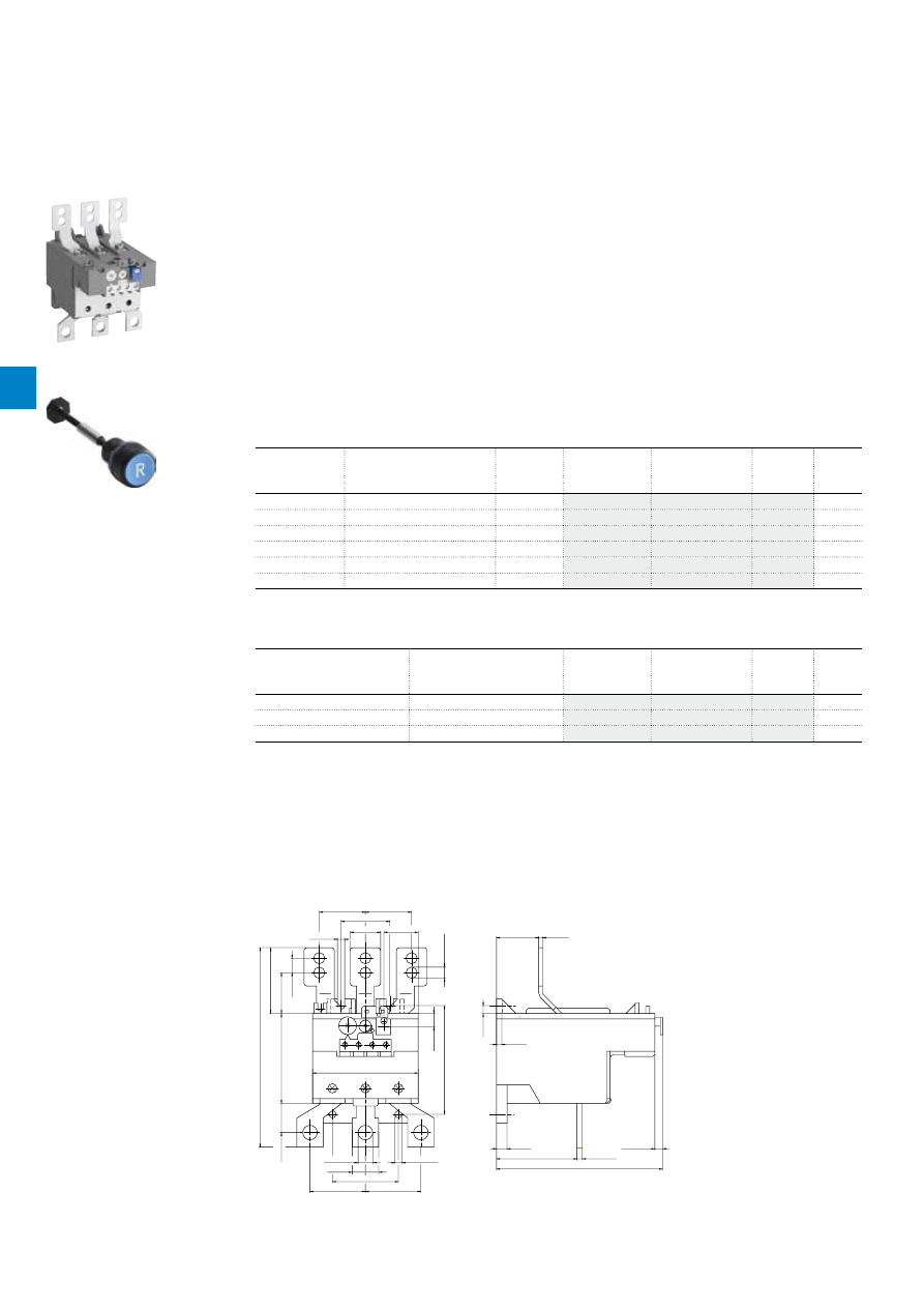
2CD
C
10
6
0
38
C
0
2
01
4
/22 |
ABB
TA200DU thermal overload relays
66 … 200 A
Description
The TA200DU thermal overload relays are economic electromechanical protection devices for the main
circuit. They offer reliable protection for motors in the event of overload or phase failure. The devices have
trip class 10A.
The thermal overload relays are three pole relays with bimetal tripping elements. The motor current flows
through the bimetal tripping elements and heats them directly and indirectly. In case of an overload (over
current), the bimetal elements bent as a result of the heating. This leads to a release of the relay and a
change of the contacts switching position (95-96 / 97-98).
– Manual or automatic reset selectable
– Phase loss sensitive acc. to IEC/EN 60947-4-1
– TEST and STOP function – Trip indication on the front
– Temperature compensation
– Suitable for three- and single-phase applications
Ordering details
Setting range
Short-circuit
protective device
Trip class
Type
Order code
Weight
(1 pce)
A
kg
66 ... 90
200 A, Fuse type gG / 125 A aM 10A
TA200DU-90
0.755
80 ... 110
224 A, Fuse type gG / 160 A aM 10A
TA200DU-110
0.760
100 ... 135
224 A, Fuse type gG / 200 A aM 10A
TA200DU-135
0.760
110 ... 150
250 A, Fuse type gG / 200 A aM 10A
TA200DU-150
0.760
130 ... 175
315 A, Fuse type gG / 250 A aM 10A
TA200DU-175
0.770
150 ... 200
315 A, Fuse type gG / 250 A aM 10A
TA200DU-200
0.785
Ordering details accessories
For thermal overload relays
Description
Type
Order code
Weight
(1 pce)
A
kg
TA200DU
Terminal shroud
LT200/A
0.090
TA200DU
Single mounting kit
DB200
0.225
TA200DU
Reset push button*
KPR-101L
0.027
*Note: for more information see catalogie 1SFC151004C0201
2CDC231016F0013
TA200DU
Main dimensions
mm,
inches
4
0.16"
61
2.4"
8
0.31"
126
4.96"
6
0.24"
4
0.16"
6
0.24"
32
1.26"
3
0.12"
23
0.91"
26
1.02"
37
1.46"
35
1.38"
35
1.38"
Ø8.5
Ø0.33"
5.5
0.22"
82.3
3.24"
11
0.43"
30.9
1.22"
49.9
2"
151
5.94"
10
0.39"
68
2.68"
80
3.15"
Ø 11
Ø 0.43"
20
0.79"
22.1
0.87"
Ø 5.3
Ø 0.21"
42
1.65"
42
1.65"
50
1.97"
2CDC232021F0011
TA200DU
1SFC151402F0001
KPR-101L
4

2CD
C
10
6
0
38
C
0
2
01
ABB
|
4
/23
Main circuit – Utilization characteristics according to IEC/EN
Type
TA200DU
Standards
IEC/EN 60947-1, IEC/EN 60947-4-1
Rated operational voltage U
e
690 V AC
Rated frequency
DC, 50/60 Hz
Frequency range
0 ... 400 Hz
Trip class
10A
Number of poles
3
Duty time
100 %
Operating frequency without early tripping
Up to 15 operations/h, see "Technical diagram – Intermittent periodic duty"
Rated impulse withstand voltage U
imp
6 kV
Rated insulation voltage U
i
690 V AC
Auxiliary circuit according to IEC/EN
Type
TA200DU
Rated operational voltage U
e
500 V AC, 440 V DC
Conventional free air thermal current I
th
N.C., 95-96
10 A
N.O., 97-98
6 A
Rated frequency
DC, 50/60 Hz
Number of poles
1 N.O. + 1 N.C.
I
e
/ Rated operational current AC-15
acc. to IEC/EN 60947-5-1 for utilization category
110-120 V
N.C., 95-96
3.00 A
N.O., 97-98
1.50 A
220-230-240 V
N.C., 95-96
3.00 A
N.O., 97-98
1.50 A
440 V
N.C., 95-96
1.00 A
N.O., 97-98
1.00 A
480-500 V
N.C., 95-96
1.00 A
N.O., 97-98
1.00 A
I
e
/ Rated operational current DC-13
acc. to IEC/EN 60947-5-1 for utilization category
24 V
N.C., 95-96
1.25 A
N.O., 97-98
1.25 A
60 V
N.C., 95-96
0.25 A
N.O., 97-98
0.25 A
110-120-125 V
N.C., 95-96
0.25 A
N.O., 97-98
0.25 A
250 V
N.C., 95-96
0.12 A
N.O., 97-98
0.04 A
Minimum switching capacity
17 V / 3 mA
Short-circuit protective device
N.C., 95-96
10 A, Fuse type gG
N.O., 97-98
6 A, Fuse type gG
Rated impulse withstand voltage U
imp
6 kV
Rated insulation voltage U
i
690 V
Technical diagram – Intermittent periodic duty
140
120
0
20
40
60
80
100
0
20
40
60
80 100 (%)
t = 1
s
a
t = 1.5
s
a
t = 3
s
a
t = 5 s
a
t = 0.5
s
a
duty ratio
switching fr
equency
(Op/h)
2CDC232005F0211
t
a
: Motor starting time
TA200DU thermal overload relays
Technical data
4
2CD
C
10
6
0
38
C
0
2
01
4
/24 |
ABB
Main circuit – Utilization characteristics according to UL/CSA
Type
TA200DU
Standards
UL 508, CSA 22.2 No. 14
Maximum operational voltage
600 V AC
Trip rating
125 % of FLA
Full load amps (FLA)
See table "Full load amps and short-circuit protective device"
Short-circuit rating RMS symmetrical
See table "Full load amps and short-circuit protective device"
Short-circuit protective device
See table "Full load amps and short-circuit protective device"
Auxiliary circuit according to UL/CSA
Type
TA200DU
Contact rating
N.C., 95-96
C600
N.O., 97-98
B600
Conventional thermal current
5 A
Full load amps and short-circuit protective device
Type
Full load amps
(FLA)
Short-circuit protective device
480 / 600 V AC
Short circuit rating
RMS symmetrical
Fuse type
Listed circuit
breaker
Short circuit rating
RMS symmetrical
Fuse type
Short circuit rating
RMS symmetrical
Listed circuit
breaker
TA200DU-90
90 A
10 kA
250 A, K5 / RK5 225 A
100 kA
250 A, Class J
100 kA
250 A
TA200DU-110
110 A
10 kA
250 A, K5 / RK5 225 A
100 kA
250 A, Class J
100 kA
250 A
TA200DU-135
135 A
10 kA
300 A, K5 / RK5 225 A
100 kA
250 A, Class J
100 kA
250 A
TA200DU-150
150 A
10 kA
300 A, K5 / RK5 225 A
100 kA
250 A, Class J
100 kA
250 A
TA200DU-175
175 A
10 kA
300 A, K5 / RK5 225 A
100 kA
300 A, Class J
100 kA
300 A
TA200DU-200
200 A
10 kA
400 A, K5 / RK5 400 A
100 kA
400 A, Class J
100 kA
400 A
TA200DU thermal overload relays
Technical data
4
2CD
C
10
6
0
38
C
0
2
01
ABB
|
4
/25
General technical data
Type
TA200DU
Pollution degree
3
Phase loss sensitive
Yes
Ambient air temperature
Operation
Open - compensated
-25 ... +55 °C
Open
-25 ... +55 °C
Storage
-40 ... +70 °C
Ambient air temperature compensation
Acc. to IEC/EN60947-4-1
Maximum operating altitude permissible
2000 m
Resistance to shock acc. to IEC 60068-2-27
12g / 15 ms
Mounting position
Position 1-6
Mounting
Mount on the contactor and tighten the screws of the main circuit terminals or with single
mounting kit
Degree of protection
Housing
IP20
Main circuit terminals
IP00
Electrical connection
Main circuit
Type
TA200DU
Connecting capacity
Rigid
1 x
25 ... 120 mm²
Flexible
1 x
25 ... 120 mm²
Stranded acc. to UL/CSA
1 x
AWG 4 ... 0000
Flexible acc. to UL/CSA
1 x
AWG 4 ... 0000
Lugs
L > 10 mm
Tightening torques
25 Nm / 220 lb.in
Connection screw
Open bars
Auxiliary circuit
Type
TA200DU
Connecting capacity
Rigid
1 x or 2 x
0.75 ... 4 mm²
Flexible with ferrule
1 x or 2 x
0.75 ... 2.5 mm²
Flexible with insulated ferrule
1 x or 2 x
0.75 ... 2.5 mm²
Flexible
1 x or 2 x
0.75 ... 2.5 mm²
Stranded acc. to UL/CSA
1 x or 2 x
AWG 18 ... 14
Flexible acc. to UL/CSA
1 x or 2 x
AWG 18 ... 14
Stripping length
9 mm
Tightening torques
0.8 ... 1.3 Nm / 12 Ib.in
Connection screw
M3.5 (Pozidriv 2)
TA200DU thermal overload relays
Technical data
4
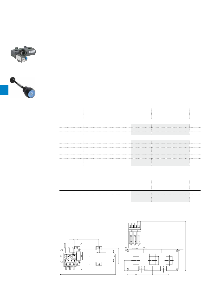
2CDC106041C0201
4
/26 |
ABB
TA450DU, TA450SU thermal overload relays
40 ... 310 A
Description
The TA450DU, TA450SU thermal overload relays are economic electromechanical protection devices for
the main circuit. They offer reliable protection for motors in the event of overload or phase failure. The
TA450DU devices have trip class 10A, the TA450SU devices have trip class 30.
The thermal overload relays are three pole relays with bimetal tripping elements. The motor current flows
through the bimetal tripping elements and heats them directly and indirectly. In case of an overload (over
current), the bimetal elements bent as a result of the heating. This leads to a release of the relay and a
change of the contacts switching position (95-96 / 97-98).
– Manual or automatic reset selectable
– Phase loss sensitive acc. to IEC/EN 60947-4-1
– Two electrically isolated auxiliary contacts – 1 N.O. + 1 N.C.
– TEST and STOP function – Trip indication on the front
– Temperature compensation
– Suitable for three- and single-phase applications
Ordering details
Setting range
Short-circuit
protective device
Trip class
Type
Order code
Weight
(1 pce)
A
kg
Thermal overload relays TA450DU
130 ... 185
not applicable
10A
TA450DU-185
1.500
165 ... 235
not applicable
10A
TA450DU-235
1.500
220 ... 310
not applicable
10A
TA450DU-310
1.500
Thermal overload relays TA450SU
40 … 60
not applicable
30
TA450SU-60
1.500
55 … 80
not applicable
30
TA450SU-80
1.500
70 … 105
not applicable
30
TA450SU-105
1.500
95 … 140
not applicable
30
TA450SU-140
1.500
130 … 185
not applicable
30
TA450SU-185
1.500
165 … 235
not applicable
30
TA450SU-235
1.500
220 … 310
not applicable
30
TA450SU-310
1.500
Ordering details accessories
For thermal overload relays
Description
Type
Order code
Weight
(1 pce)
A
kg
TA450DU, TA450SU
Terminal shroud
DT450/A185
1.070
TA450DU, TA450SU
Terminal shroud
DT450/A300
1.180
TA450DU, TA450SU
Reset push button*
KPR-101L
0.027
*Note: for more information see catalogue 1SFC151004C0201
2CDC231011F0011
TA450DU-310
Main dimensions
mm,
inches
193
7.6"
24.5
0.96"
76.3
3"
55
2.17"
5.5
0.22"
9.1
0.36"
75.5
2.97"
35.2
1.39"
58
2.28"
58
2.28"
32
1.26"
22
0.87"
28.4
1.12"
4.5
0.18"
173.4
6.83"
6
0.24"
2CDC232022F0011
TA450DU, TA450SU
1SFC151402F0001
KPR-101L
4

2CDC106041C0201
ABB
|
4
/27
Main circuit – Utilization characteristics according to IEC/EN
Type
TA450DU, TA450SU
Standards
IEC 60947-1 / 60947-4-1 and EN 60947-1 / 60947-4-1
Rated operational voltage U
e
1000 V AC
Rated frequency
50/60 Hz
Trip class
10A / 30
Number of poles
3
Duty time
100 %
Operating frequency without early tripping
Up to 15 operations/h, see "Technical diagram – Intermittent periodic duty"
Rated impulse withstand voltage U
imp
8 kV
Rated insulation voltage U
i
1000 V AC
Auxiliary circuit according to IEC/EN
Type
TA450DU, TA450SU
Rated operational voltage U
e
500 V AC, 440 V DC
Conventional free air thermal current I
th
N.C., 95-96
10 A
N.O., 97-98
6 A
Rated frequency
DC, 50/60 Hz
Number of poles
1 N.O. + 1 N.C.
I
e
/ Rated operational current AC-15
acc. to IEC/EN 60947-5-1 for utilization category
110-120 V
N.C., 95-96
3.00 A
N.O., 97-98
1.50 A
220-230-240 V
N.C., 95-96
3.00 A
N.O., 97-98
1.50 A
440 V
N.C., 95-96
1.00 A
N.O., 97-98
1.00 A
480-500 V
N.C., 95-96
1.00 A
N.O., 97-98
1.00 A
I
e
/ Rated operational current DC-13
acc. to IEC/EN 60947-5-1 for utilization category
24 V
N.C., 95-96
1.25 A
N.O., 97-98
1.25 A
60 V
N.C., 95-96
0.25 A
N.O., 97-98
0.25 A
110-120-125 V
N.C., 95-96
0.25 A
N.O., 97-98
0.25 A
250 V
N.C., 95-96
0.12 A
N.O., 97-98
0.04 A
Minimum switching capacity
17 V / 3 mA
Short-circuit protective device
N.C., 95-96
10 A, Fuse type gG
N.O., 97-98
6 A, Fuse type gG
Rated impulse withstand voltage U
imp
6 kV
Rated insulation voltage U
i
500 V
Technical diagram – Intermittent periodic duty
140
120
0
20
40
60
80
100
0
20
40
60
80 100 (%)
t = 1
s
a
t = 1.5
s
a
t = 3
s
a
t = 5 s
a
t = 0.5
s
a
duty ratio
switching fr
equency
(Op/h)
2CDC232005F0211
t
a
: Motor starting time
TA450DU, TA450SU thermal overload relays
Technical data
4

2CDC106041C0201
4
/28 |
ABB
Main circuit – Utilization characteristics according to UL/CSA
Type
TA450DU, TA450SU
Standards
UL 508, CSA 22.2 No. 14
Maximum operational voltage
600 V AC
Trip rating
125 % of FLA
Full load amps (FLA)
See table "Full load amps and short-circuit protective device"
Short-circuit rating RMS symmetrical
See table "Full load amps and short-circuit protective device"
Short-circuit protective device
See table "Full load amps and short-circuit protective device"
Auxiliary circuit according to UL/CSA
Type
TA450DU, TA450SU
Contact rating
N.C., 95-96
C600
N.O., 97-98
B600
Conventional thermal current
5 A
Full load amps and short-circuit protective device
Type
Full load amps (FLA)
Short-circuit protective device
480 / 600 V AC
Short circuit rating RMS symmetrical Fuse type
Listed circuit breaker
TA450DU-185
185 A
10 kA
na
na
TA450DU-235
235 A
10 kA
na
na
TA450DU-310
310 A
18 kA
na
na
TA450DU, TA450SU thermal overload relays
Technical data
4
2CDC106041C0201
ABB
|
4
/29
General technical data
Type
TA450DU, TA450SU
Pollution degree
3
Phase loss sensitive
Yes
Ambient air temperature
Operation
Open - compensated
-25 ... +55 °C
Open
-25 ... +55 °C
Storage
-40 ... +70 °C
Ambient air temperature compensation
Acc. to IEC/EN60947-4-1
Maximum operating altitude permissible
2000 m
Resistance to shock acc. to IEC 60068-2-27
12g / 15 ms
Mounting position
Position 1-6
Degree of protection
Housing
IP20
Main circuit terminals
IP10
Electrical connection
Main circuit
Type
TA450DU, TA450SU
Connecting capacity
Bar
Max. 21 x 28.4 mm
Auxiliary circuit
Type
TA450DU, TA450SU
Connecting capacity
Rigid
1 x or 2 x
0.75 ... 4 mm²
Flexible with ferrule
1 x or 2 x
0.75 ... 2.5 mm²
Flexible with insulated ferrule
1 x or 2 x
0.75 ... 2.5 mm²
Flexible
1 x or 2 x
0.75 ... 2.5 mm²
Stranded acc. to UL/CSA
1 x or 2 x
AWG 18-14
Flexible acc. to UL/CSA
1 x or 2 x
AWG 18-14
Stripping length
9 mm
Tightening torques
0.8 ... 1.3 Nm / 12 Ib.in
Connection screw
M3.5 (Pozidriv 2)
TA450DU, TA450SU thermal overload relays
Technical data
4

Coordination with short-circuit protection devices
In compliance with standards IEC 60947-4-1 and EN 60947-4-1, we define for the contactors and starters the type, rating
and characteristics of the short-circuit protection devices SCPD which allow selective protection against overloads and ensure
protection against short circuits.
Basic functions
Any starter is designed to:
– start motors,
– ensure continuous functioning of motors,
– disconnect motors from the supply line,
– guarantee protection of motors against overloads.
The starter is typically made up of a switching device (contactor) and an overload protection device (thermal overload relay or electronic overload
relay).
These two devices MUST be coordinated with equipment capable of providing protection against short circuit (SCPD: short circuit protective de-
vice): typically a circuit breaker with magnetic release only or a switch fuse. These are not necessarily part of the starter.
Applicable standards
IEC 60947-4-1 (EN 60947-4-1) precisely defines the different points to be considered in order to carry out correct coordination.
Complete coordination for a combination includes the following points:
– Selectivity test between the overload relay and the short-circuit protection device SCPD.
– Short-circuit condition tests:
- at prospective "r" currents - These currents depend on the rated operational current of the starter (
Ie
AC-3) and are given by the standard
(Table 13). For example:
r = 1kA for
Ie
AC-3 < 16 A
r = 3 kA for 16 A <
Ie
AC-3 < 63 A
r = 5 kA for 63 A <
Ie
AC-3 < 125 A etc.
- at the rated conditional short-circuit current "
Iq
" - This is the maximum prospective current that the combination can withstand, for example
50 kA.
Types of coordination
IEC 60947-4-1 (EN 60947-4-1) defines two types of coordination according to the expected level of service continuity. Acceptable extreme dam-
age for the switchgear is divided into two types.
Type 1:
In short-circuit conditions, the contactor or starter does not endanger persons or installations and will not be able to then operate without
being repaired or having parts replaced.
Type 2:
In short-circuit conditions, the contactor or starter does not endanger persons or installations and will be able to operate afterwards.
The risk of contacts light welding is acceptable. In this case, the manufacturer must stipulate the measures to be taken with respect to
maintenance of the equipment.
The complete ABB offer
ABB has acquired years of experience with respect to problems of coordination and is able to make a complete offer based on tests performed in
its qualified laboratories. This offer includes 400 V, 500 V, 690 V networks.
A complete data base of coordination tables,
according to IEC 60947-4-1 (EN 60947-4-1), is available on the ABB Website.
In the coordination tables the following short-circuit protection devices are recommended:
– Moulded case circuit-breakers (MCCBs)
– Miniature circuit-breakers (MCBs)
– Switch-disconnector-fuses (aM, gG and BS)
– Manual Motor Starters (MMS).
General remarks applicable to all tables
– Each table is defined for a maximum ambient temperature of 40 °C. For higher temperatures, apply a derating factor according to the following
rules:
- Fuses: factor of 0.8 applied to
In
for an ambient temperature of 70 °C
- MCCBs and MCBs: factor of 0.8 applied to
In
for an ambient temperature of 60 °C
- The starter derating factor depends on the operating conditions of thermal overload relays:
Factor of 0.9 applied to
In
for an ambient temperature of 70 °C.
– Each table is defined for motor currents: 3-phase motors, 4-pole
–
Normal starting
means a starting time < 2 s. -
Difficult starting
means an accelerating time 10 s <
ts
< 30 s
Tripping classes
of thermal overload relays according to IEC 60947-4-1 (EN 60947-4-1): 10A and 10
Tripping classes
of electronic overload relays according to IEC 60947-4-1 (EN 60947-4-1): 10E, 20E, 30E selectable
– In the tables with MCCBs, these are fitted with the magnetic relay alone. Setting is always carried out at > 12.3
Ie
AC-3 so that the transient
current peak occurring during starting does not lead to tripping.
1S
B
C
10
15
9
0
S
0
2
01 - R
ev
. A
5
5
/0 |
ABB
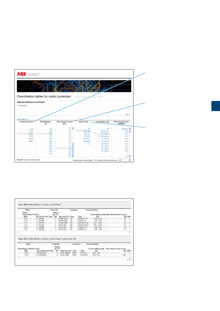
Coordination with short-circuit protection devices
A complete data base of coordination tables, according to
IEC 60947-4-1
(EN 60947-4-1)
or UL 508 / UL 60947-4-1
, is available on the ABB
Website: see below.
Selection
Simple or multiple selections all from the same screen.
Results
– Search results displayed at the bottom of the selection page.
– Only the most appropriate solutions to your application, will be displayed at the bottom of the page.
"Enable Smart Current Search" function featured for the short-circuit current where "near to" selected values also are included in the result.
– Possible to print the page to a pdf file or from your printer.
– "Clear selection" function to deselect all selected.
Access
To find the coordination tables for motor protection, please see:
www.abb.com/lowvoltage
then go to the right menu: "Support", select: "
Online Product Selection Tools
" then select "
Coordination Tables for
motor protection
"
Short-circuit protection devices
– Air circuit breakers
– Fuses "gG" or "aM"
– Miniature circuit breaker
– Moulded case circuit breaker
– Manual motor starter
Starter type
– Direct-on-line normal start
– Direct-on-line heavy duty
– Star-delta normal start
– Soft starter normal start
Coordination
– IEC type 1 or type 2
– UL type A to Type F
1S
B
C
10
15
91
S
0
2
01
-
R
ev
. A
ABB
|
5
/1
5

1S
B
C
10
01
79
C
0
2
01
_C
ha
p
0
6
_I
nd
ex
6
/0 |
ABB
Index
Order code classification
Order code
Type
Page
Order code
Type
Page
Order code
Type
Page
1SAM101923R0002 MSMN
2/38
1SAM101923R0012 MSMNO
2/38
1SAM201901R1001 HKF1-11
2/17
1SAM201901R1002 HKF1-20
2/17
1SAM201902R1001 HK1-11
2/17
1SAM201902R1002 HK1-20
2/17
1SAM201902R1003 HK1-02
2/17
1SAM201902R1004 HK1-20L
2/17
1SAM201903R1001 SK1-11
2/17
1SAM201903R1002 SK1-20
2/17
1SAM201903R1003 SK1-02
2/17
1SAM201904R1001 UA1-24
2/18
1SAM201904R1002 UA1-48
2/18
1SAM201904R1003 UA1-60
2/18
1SAM201904R1004 UA1-110
2/18
1SAM201904R1005 UA1-230
2/18
1SAM201904R1006 UA1-400
2/18
1SAM201904R1007 UA1-415
2/18
1SAM201904R1008 UA1-208
2/18
1SAM201906R1102 PS1-2-0-65
2/21
1SAM201906R1103 PS1-3-0-65
2/21
1SAM201906R1104 PS1-4-0-65
2/21
1SAM201906R1105 PS1-5-0-65
2/21
1SAM201906R1112 PS1-2-1-65
2/21
1SAM201906R1113 PS1-3-1-65
2/21
1SAM201906R1114 PS1-4-1-65
2/21
1SAM201906R1115 PS1-5-1-65
2/21
1SAM201906R1122 PS1-2-2-65
2/21
1SAM201906R1123 PS1-3-2-65
2/21
1SAM201906R1124 PS1-4-2-65
2/21
1SAM201906R1125 PS1-5-2-65
2/21
1SAM201907R1101 S1-M1-25
2/21
1SAM201907R1102 S1-M2-25
2/21
1SAM201907R1103 S1-M3-25
2/21
1SAM201908R1001 BS1-3
2/21
1SAM201909R1001 FS116
2/21
1SAM201909R1021 MSAH1
2/38
1SAM201910R1001 AA1-24
2/18
1SAM201910R1002 AA1-110
2/18
1SAM201910R1003 AA1-230
2/18
1SAM201910R1004 AA1-400
2/18
1SAM201911R1010 IB132-G
2/23
1SAM201911R1011 IB132-Y
2/23
1SAM201912R1010 DMS132-G
2/23
1SAM201912R1011 DMS132-Y
2/23
1SAM201913R1103 S1-M3-35
2/21
1SAM201916R1103 PS1-3-0-100
2/21
1SAM201916R1104 PS1-4-0-100
2/21
1SAM201916R1105 PS1-5-0-100
2/21
1SAM201916R1113 PS1-3-1-100
2/21
1SAM201916R1114 PS1-4-1-100
2/21
1SAM201916R1115 PS1-5-1-100
2/21
1SAM201916R1123 PS1-3-2-100
2/21
1SAM201920R1000 MSH-AR
2/38
1SAM201920R1001 MSHD-LB
2/38
1SAM201920R1002 MSHD-LY
2/38
1SAM201920R1011 MSHD-LTB
2/38
1SAM201920R1012 MSHD-LTY
2/38
1SAM250000R1001 MS116-0.16
2/4
1SAM250000R1002 MS116-0.25
2/4
1SAM250000R1003 MS116-0.4
2/4
1SAM250000R1004 MS116-0.63
2/4
1SAM250000R1005 MS116-1.0
2/4
1SAM250000R1006 MS116-1.6
2/4
1SAM250000R1007 MS116-2.5
2/4
1SAM250000R1008 MS116-4.0
2/4
1SAM250000R1009 MS116-6.3
2/4
1SAM250000R1010 MS116-10
2/4
1SAM250000R1011 MS116-16
2/4
1SAM250000R1012 MS116-12
2/4
1SAM250000R1013 MS116-20
2/4
1SAM250000R1014 MS116-25
2/4
1SAM250000R1015 MS116-32
2/4
1SAM250005R1001 MS116-0.16-HKF1-11 2/4
1SAM250005R1002 MS116-0.25-HKF1-11 2/4
1SAM250005R1003 MS116-0.4-HKF1-11 2/4
1SAM250005R1004 MS116-0.63-HKF1-11 2/4
1SAM250005R1005 MS116-1.0-HKF1-11 2/4
1SAM250005R1006 MS116-1.6-HKF1-11 2/4
1SAM250005R1007 MS116-2.5-HKF1-11 2/4
1SAM250005R1008 MS116-4.0-HKF1-11 2/4
1SAM250005R1009 MS116-6.3-HKF1-11 2/4
1SAM250005R1010 MS116-10.0-HKF1-11 2/4
1SAM250005R1011 MS116-16.0-HKF1-11 2/4
1SAM250005R1012 MS116-12.0-HKF1-11 2/4
1SAM250005R1013 MS116-20-HKF1-11 2/4
1SAM250005R1014 MS116-25-HKF1-11 2/4
1SAM250005R1015 MS116-32-HKF1-11 2/4
1SAM301901R1001 CK1-11
2/17
1SAM301901R1002 CK1-20
2/17
1SAM301901R1003 CK1-02
2/17
1SAM350000R1001 MS132-0.16
2/8
1SAM350000R1002 MS132-0.25
2/8
1SAM350000R1003 MS132-0.4
2/8
1SAM350000R1004 MS132-0.63
2/8
1SAM350000R1005 MS132-1.0
2/8
1SAM350000R1006 MS132-1.6
2/8
1SAM350000R1007 MS132-2.5
2/8
1SAM350000R1008 MS132-4.0
2/8
1SAM350000R1009 MS132-6.3
2/8
1SAM350000R1010 MS132-10
2/8
1SAM350000R1011 MS132-16
2/8
1SAM350000R1012 MS132-12
2/8
1SAM350000R1013 MS132-20
2/8
1SAM350000R1014 MS132-25
2/8
1SAM350000R1015 MS132-32
2/8
1SAM350005R1001 MS132-0.16-HKF1-11 2/8
1SAM350005R1002 MS132-0.25-HKF1-11 2/8
1SAM350005R1003 MS132-0.4-HKF1-11 2/8
1SAM350005R1004 MS132-0.63-HKF1-11 2/8
1SAM350005R1005 MS132-1.0-HKF1-11 2/8
1SAM350005R1006 MS132-1.6-HKF1-11 2/8
1SAM350005R1007 MS132-2.5-HKF1-11 2/8
1SAM350005R1008 MS132-4.0-HKF1-11 2/8
1SAM350005R1009 MS132-6.3-HKF1-11 2/8
1SAM350005R1010 MS132-10.0-HKF1-11 2/8
1SAM350005R1011 MS132-16.0-HKF1-11 2/8
1SAM350005R1012 MS132-12.0-HKF1-11 2/8
1SAM350005R1013 MS132-20-HKF1-11 2/8
1SAM350005R1014 MS132-25-HKF1-11 2/8
1SAM350005R1015 MS132-32-HKF1-11 2/8
1SAM360000R1001 MO132-0.16
2/12
1SAM360000R1002 MO132-0.25
2/12
1SAM360000R1003 MO132-0.4
2/12
1SAM360000R1004 MO132-0.63
2/12
1SAM360000R1005 MO132-1.0
2/12
1SAM360000R1006 MO132-1.6
2/12
1SAM360000R1007 MO132-2.5
2/12
1SAM360000R1008 MO132-4.0
2/12
1SAM360000R1009 MO132-6.3
2/12
1SAM360000R1010 MO132-10
2/12
1SAM360000R1011 MO132-16
2/12
1SAM360000R1012 MO132-12
2/12
1SAM360000R1013 MO132-20
2/12
1SAM360000R1014 MO132-25
2/12
1SAM360000R1015 MO132-32
2/12
1SAM401901R1001 HK4-11
2/33
1SAM401901R1002 HK4-W
2/33
1SAM401902R1001 HKS4-11
2/33
1SAM401902R1002 HKS4-20
2/33
1SAM401902R1003 HKS4-02
2/33
1SAM401904R1001 SK4-11
2/33
1SAM401905R1001 UA4-110
2/33
1SAM401905R1002 UA4-230
2/33
1SAM401905R1003 UA4-400
2/33
1SAM401905R1004 UA4-24
2/33
1SAM401906R1001 UA4-HK-230
2/33
1SAM401906R1002 UA4-HK-400
2/33
1SAM401907R1001 AA4-24
2/33
1SAM401907R1002 AA4-110
2/33
1SAM401907R1003 AA4-230
2/33
1SAM401907R1004 AA4-400
2/33
1SAM401908R1001 KA450
2/36
1SAM401910R1001 TB450
2/36
1SAM401911R1001 PS4-2-0
2/36
1SAM401911R1002 PS4-3-0
2/36
1SAM401911R1003 PS4-4-0
2/36
1SAM401911R1004 PS4-2-2
2/36
1SAM401911R1005 PS4-3-2
2/36
1SAM401911R1006 PS4-4-2
2/36
1SAM401911R1007 S4-M1
2/36
1SAM401911R1008 BS4-3
2/36
1SAM401912R1001 DX495
2/36
1SAM450000R1005 MS450-40
2/24
1SAM450000R1006 MS450-45
2/24
6

1S
B
C
10
01
79
C
0
2
01
_C
ha
p
0
6
_I
nd
ex
1S
B
C
10
01
79
C
0
2
01
_C
ha
p
0
6
_I
nd
ex
ABB
|
6
/1
Index
Order code classification
Order code
Type
Page
Order code
Type
Page
Order code
Type
Page
1SAM450000R1007 MS450-50
2/24
1SAM460000R1005 MO450-40
2/28
1SAM460000R1006 MO450-45
2/28
1SAM460000R1007 MO450-50
2/28
1SAM501901R1001 KA495
2/36
1SAM501902R1001 KA495C
2/36
1SAM550000R1007 MS495-63
2/24
1SAM550000R1008 MS495-75
2/24
1SAM550000R1009 MS495-90
2/24
1SAM550000R1010 MS495-100
2/24
1SAM560000R1007 MO495-63
2/28
1SAM560000R1008 MO495-75
2/28
1SAM560000R1009 MO495-90
2/28
1SAM560000R1010 MO495-100
2/28
1SAM580000R1004 MS497-32
2/24
1SAM580000R1005 MS497-40
2/24
1SAM580000R1006 MS497-50
2/24
1SAM580000R1007 MS497-63
2/24
1SAM580000R1008 MS497-75
2/24
1SAM580000R1009 MS497-90
2/24
1SAM580000R1010 MS497-100
2/24
1SAM590000R1004 MO496-32
2/28
1SAM590000R1005 MO496-40
2/28
1SAM590000R1006 MO496-50
2/28
1SAM590000R1007 MO496-63
2/28
1SAM590000R1008 MO496-75
2/28
1SAM590000R1009 MO496-90
2/28
1SAM590000R1010 MO496-100
2/28
1SAZ201108R0001 DB25/25A
4/7
1SAZ201108R0002 DB25/32A
4/7
1SAZ201307R0002 DX25
4/7
1SAZ201504R0001 DR25-A-24
4/7
1SAZ201504R0002 DR25-A-48
4/7
1SAZ201504R0003 DR25-A-110
4/7
1SAZ201504R0005 DR25-A-220/380
4/7
1SAZ201504R0006 DR25-A-500
4/7
1SAZ211201R2005 TA25DU-0.16M
4/4
1SAZ211201R2009 TA25DU-0.25M
4/4
1SAZ211201R2013 TA25DU-0.4M
4/4
1SAZ211201R2017 TA25DU-0.63M
4/4
1SAZ211201R2021 TA25DU-1.0M
4/4
1SAZ211201R2023 TA25DU-1.4M
4/4
1SAZ211201R2025 TA25DU-1.8M
4/4
1SAZ211201R2028 TA25DU-2.4M
4/4
1SAZ211201R2031 TA25DU-3.1M
4/4
1SAZ211201R2033 TA25DU-4.0M
4/4
1SAZ211201R2035 TA25DU-5.0M
4/4
1SAZ211201R2038 TA25DU-6.5M
4/4
1SAZ211201R2040 TA25DU-8.5M
4/4
1SAZ211201R2043 TA25DU-11M
4/4
1SAZ211201R2045 TA25DU-14M
4/4
1SAZ211201R2047 TA25DU-19M
4/4
1SAZ211201R2051 TA25DU-25M
4/4
1SAZ211201R2053 TA25DU-32M
4/4
1SAZ301110R0001 DB80
4/8
1SAZ311201R2001 TA42DU-25M
4/8
1SAZ311201R2002 TA42DU-32M
4/8
1SAZ311201R2003 TA42DU-42M
4/8
1SAZ321201R2001 TA75DU-25M
4/11
1SAZ321201R2002 TA75DU-32M
4/11
1SAZ321201R2003 TA75DU-42M
4/11
1SAZ321201R2004 TA75DU-52M
4/11
1SAZ321201R2005 TA75DU-63M
4/11
1SAZ321201R2006 TA75DU-80M
4/11
1SAZ331201R1003 TA80DU-42
4/14
1SAZ331201R1004 TA80DU-52
4/14
1SAZ331201R1005 TA80DU-63
4/14
1SAZ331201R1006 TA80DU-80
4/14
1SAZ401110R0001 DB200
4/18
1SAZ401901R1001 LT200/A
4/22
1SAZ411201R1001 TA110DU-90
4/18
1SAZ411201R1002 TA110DU-110
4/18
1SAZ421201R1001 TA200DU-90
4/22
1SAZ421201R1002 TA200DU-110
4/22
1SAZ421201R1003 TA200DU-135
4/22
1SAZ421201R1004 TA200DU-150
4/22
1SAZ421201R1005 TA200DU-175
4/22
1SAZ421201R1006 TA200DU-200
4/22
1SAZ501901R1001 DT450/A185
4/26
1SAZ501902R1001 DT450/A300
4/26
1SAZ511201R1001 TA450DU-185
4/26
1SAZ511201R1002 TA450DU-235
4/26
1SAZ511201R1003 TA450DU-310
4/26
1SAZ611201R1001 TA450SU-185
4/26
1SAZ611201R1002 TA450SU-235
4/26
1SAZ611201R1003 TA450SU-310
4/26
1SAZ611201R1005 TA450SU-60
4/26
1SAZ611201R1006 TA450SU-80
4/26
1SAZ611201R1007 TA450SU-105
4/26
1SAZ611201R1008 TA450SU-140
4/26
1SBH141001R8022 N22E
3/45
1SBH141001R8031 N31E
3/45
1SBH141001R8040 N40E
3/45
1SBH141001R8122 N22E
3/45
1SBH141001R8131 N31E
3/45
1SBH141001R8140 N40E
3/45
1SBH141001R8322 N22E
3/45
1SBH141001R8331 N31E
3/45
1SBH141001R8340 N40E
3/45
1SBH141001R8422 N22E
3/45
1SBH141001R8431 N31E
3/45
1SBH141001R8440 N40E
3/45
1SBH141001R8522 N22E
3/45
1SBH141001R8531 N31E
3/45
1SBH141001R8540 N40E
3/45
1SBH141001R8622 N22E
3/45
1SBH141001R8631 N31E
3/45
1SBH141001R8640 N40E
3/45
1SBH141001R8822 N22E
3/45
1SBH141001R8831 N31E
3/45
1SBH141001R8840 N40E
3/45
1SBL141001R8001 A9-30-01
3/4
1SBL141001R8010 A9-30-10
3/4
1SBL141001R8101 A9-30-01
3/4
1SBL141001R8110 A9-30-10
3/4
1SBL141001R8301 A9-30-01
3/4
1SBL141001R8310 A9-30-10
3/4
1SBL141001R8401 A9-30-01
3/4
1SBL141001R8410 A9-30-10
3/4
1SBL141001R8501 A9-30-01
3/4
1SBL141001R8510 A9-30-10
3/4
1SBL141001R8601 A9-30-01
3/4
1SBL141001R8610 A9-30-10
3/4
1SBL141001R8801 A9-30-01
3/4
1SBL141001R8810 A9-30-10
3/4
1SBL141201R8000 A9-40-00
3/31
1SBL141201R8100 A9-40-00
3/31
1SBL141201R8300 A9-40-00
3/31
1SBL141201R8400 A9-40-00
3/31
1SBL141201R8500 A9-40-00
3/31
1SBL141201R8600 A9-40-00
3/31
1SBL141201R8800 A9-40-00
3/31
1SBL141501R8000 A9-22-00
3/31
1SBL141501R8100 A9-22-00
3/31
1SBL141501R8300 A9-22-00
3/31
1SBL141501R8400 A9-22-00
3/31
1SBL141501R8500 A9-22-00
3/31
1SBL141501R8600 A9-22-00
3/31
1SBL141501R8800 A9-22-00
3/31
1SBL161001R8001 A12-30-01
3/4
1SBL161001R8010 A12-30-10
3/4
1SBL161001R8101 A12-30-01
3/4
1SBL161001R8110 A12-30-10
3/4
1SBL161001R8301 A12-30-01
3/4
1SBL161001R8310 A12-30-10
3/4
1SBL161001R8401 A12-30-01
3/4
1SBL161001R8410 A12-30-10
3/4
1SBL161001R8501 A12-30-01
3/4
1SBL161001R8510 A12-30-10
3/4
1SBL161001R8601 A12-30-01
3/4
1SBL161001R8610 A12-30-10
3/4
1SBL161001R8801 A12-30-01
3/4
1SBL161001R8810 A12-30-10
3/4
1SBL181001R8001 A16-30-01
3/4
1SBL181001R8010 A16-30-10
3/4
1SBL181001R8101 A16-30-01
3/4
1SBL181001R8110 A16-30-10
3/4
1SBL181001R8301 A16-30-01
3/4
1SBL181001R8310 A16-30-10
3/4
1SBL181001R8401 A16-30-01
3/4
1SBL181001R8410 A16-30-10
3/4
1SBL181001R8501 A16-30-01
3/4
1SBL181001R8510 A16-30-10
3/4
1SBL181001R8601 A16-30-01
3/4
1SBL181001R8610 A16-30-10
3/4
6

1S
B
C
10
01
79
C
0
2
01
_C
ha
p
0
6
_I
nd
ex
6
/2 |
ABB
Index
Order code classification
Order code
Type
Page
Order code
Type
Page
Order code
Type
Page
1SBL181001R8801 A16-30-01
3/4
1SBL181001R8810 A16-30-10
3/4
1SBL181201R8000 A16-40-00
3/31
1SBL181201R8100 A16-40-00
3/31
1SBL181201R8300 A16-40-00
3/31
1SBL181201R8400 A16-40-00
3/31
1SBL181201R8500 A16-40-00
3/31
1SBL181201R8600 A16-40-00
3/31
1SBL181201R8800 A16-40-00
3/31
1SBL181501R8000 A16-22-00
3/31
1SBL181501R8100 A16-22-00
3/31
1SBL181501R8300 A16-22-00
3/31
1SBL181501R8400 A16-22-00
3/31
1SBL181501R8500 A16-22-00
3/31
1SBL181501R8600 A16-22-00
3/31
1SBL181501R8800 A16-22-00
3/31
1SBL241001R8001 A26-30-01
3/5
1SBL241001R8010 A26-30-10
3/5
1SBL241001R8101 A26-30-01
3/5
1SBL241001R8110 A26-30-10
3/5
1SBL241001R8301 A26-30-01
3/5
1SBL241001R8310 A26-30-10
3/5
1SBL241001R8401 A26-30-01
3/5
1SBL241001R8410 A26-30-10
3/5
1SBL241001R8501 A26-30-01
3/5
1SBL241001R8510 A26-30-10
3/5
1SBL241001R8601 A26-30-01
3/5
1SBL241001R8610 A26-30-10
3/5
1SBL241001R8801 A26-30-01
3/5
1SBL241001R8810 A26-30-10
3/5
1SBL241201R8000 A26-40-00
3/32
1SBL241201R8100 A26-40-00
3/32
1SBL241201R8300 A26-40-00
3/32
1SBL241201R8400 A26-40-00
3/32
1SBL241201R8500 A26-40-00
3/32
1SBL241201R8600 A26-40-00
3/32
1SBL241201R8800 A26-40-00
3/32
1SBL241501R8000 A26-22-00
3/32
1SBL241501R8100 A26-22-00
3/32
1SBL241501R8300 A26-22-00
3/32
1SBL241501R8400 A26-22-00
3/32
1SBL241501R8500 A26-22-00
3/32
1SBL241501R8600 A26-22-00
3/32
1SBL241501R8800 A26-22-00
3/32
1SBL281001R8001 A30-30-01
3/5
1SBL281001R8010 A30-30-10
3/5
1SBL281001R8101 A30-30-01
3/5
1SBL281001R8110 A30-30-10
3/5
1SBL281001R8301 A30-30-01
3/5
1SBL281001R8310 A30-30-10
3/5
1SBL281001R8401 A30-30-01
3/5
1SBL281001R8410 A30-30-10
3/5
1SBL281001R8501 A30-30-01
3/5
1SBL281001R8510 A30-30-10
3/5
1SBL281001R8601 A30-30-01
3/5
1SBL281001R8610 A30-30-10
3/5
1SBL281001R8801 A30-30-01
3/5
1SBL281001R8810 A30-30-10
3/5
1SBL321001R8001 A40-30-01
3/5
1SBL321001R8010 A40-30-10
3/5
1SBL321001R8101 A40-30-01
3/5
1SBL321001R8110 A40-30-10
3/5
1SBL321001R8301 A40-30-01
3/5
1SBL321001R8310 A40-30-10
3/5
1SBL321001R8401 A40-30-01
3/5
1SBL321001R8410 A40-30-10
3/5
1SBL321001R8501 A40-30-01
3/5
1SBL321001R8510 A40-30-10
3/5
1SBL321001R8601 A40-30-01
3/5
1SBL321001R8610 A40-30-10
3/5
1SBL321001R8801 A40-30-01
3/5
1SBL321001R8810 A40-30-10
3/5
1SBL331201R8000 A45-40-00
3/33
1SBL331201R8100 A45-40-00
3/33
1SBL331201R8300 A45-40-00
3/33
1SBL331201R8400 A45-40-00
3/33
1SBL331201R8500 A45-40-00
3/33
1SBL331201R8600 A45-40-00
3/33
1SBL331201R8800 A45-40-00
3/33
1SBL331501R8000 A45-22-00
3/33
1SBL331501R8100 A45-22-00
3/33
1SBL331501R8300 A45-22-00
3/33
1SBL331501R8400 A45-22-00
3/33
1SBL331501R8500 A45-22-00
3/33
1SBL331501R8600 A45-22-00
3/33
1SBL331501R8800 A45-22-00
3/33
1SBL351001R8011 A50-30-11
3/6
1SBL351001R8111 A50-30-11
3/6
1SBL351001R8311 A50-30-11
3/6
1SBL351001R8411 A50-30-11
3/6
1SBL351001R8511 A50-30-11
3/6
1SBL351001R8611 A50-30-11
3/6
1SBL351001R8811 A50-30-11
3/6
1SBL351201R8000 A50-40-00
3/33
1SBL351201R8100 A50-40-00
3/33
1SBL351201R8300 A50-40-00
3/33
1SBL351201R8400 A50-40-00
3/33
1SBL351201R8500 A50-40-00
3/33
1SBL351201R8600 A50-40-00
3/33
1SBL351201R8800 A50-40-00
3/33
1SBL371001R8011 A63-30-11
3/6
1SBL371001R8111 A63-30-11
3/6
1SBL371001R8311 A63-30-11
3/6
1SBL371001R8411 A63-30-11
3/6
1SBL371001R8511 A63-30-11
3/6
1SBL371001R8611 A63-30-11
3/6
1SBL371001R8811 A63-30-11
3/6
1SBL411001R8011 A75-30-11
3/6
1SBL411001R8111 A75-30-11
3/6
1SBL411001R8311 A75-30-11
3/6
1SBL411001R8411 A75-30-11
3/6
1SBL411001R8511 A75-30-11
3/6
1SBL411001R8611 A75-30-11
3/6
1SBL411001R8811 A75-30-11
3/6
1SBL411201R8000 A75-40-00
3/33
1SBL411201R8100 A75-40-00
3/33
1SBL411201R8300 A75-40-00
3/33
1SBL411201R8400 A75-40-00
3/33
1SBL411201R8500 A75-40-00
3/33
1SBL411201R8600 A75-40-00
3/33
1SBL411201R8800 A75-40-00
3/33
1SBL411501R8000 A75-22-00
3/33
1SBL411501R8100 A75-22-00
3/33
1SBL411501R8300 A75-22-00
3/33
1SBL411501R8400 A75-22-00
3/33
1SBL411501R8500 A75-22-00
3/33
1SBL411501R8600 A75-22-00
3/33
1SBL411501R8800 A75-22-00
3/33
1SBN010010R1001 CA5-01
3/9
1SBN010010R1010 CA5-10
3/9
1SBN010011R1001 CC5-01
3/52
1SBN010011R1010 CC5-10
3/52
1SBN010013R1001 CB5-01
3/68
1SBN010013R1010 CB5-10
3/68
1SBN010020R1011 CAL5-11
3/9
1SBN010040R1004 CA5-04E
3/52
1SBN010040R1018 CA5-11/11E
3/52
1SBN010040R1022 CA5-22E
3/9
1SBN010040R1031 CA5-31E
3/52
1SBN010040R1040 CA5-40E
3/52
1SBN010040R1104 CA5-04M
3/52
1SBN010040R1113 CA5-13M
3/52
1SBN010040R1118 CA5-11/11M
3/52
1SBN010040R1122 CA5-22M
3/9
1SBN010040R1131 CA5-31M
3/52
1SBN010040R1204 CA5-04N
3/52
1SBN010040R1213 CA5-13N
3/52
1SBN010040R1222 CA5-22N
3/47
1SBN010040R1231 CA5-31N
3/52
1SBN010040R1240 CA5-40N
3/52
1SBN010040R1304 CA5-04U
3/52
1SBN010040R1322 CA5-22U
3/9
1SBN010040R1331 CA5-31U
3/52
1SBN010040R1340 CA5-40U
3/52
1SBN011421R1008 CCL5-11
3/52
1SBN020010R1001 TE5S-24
3/60
1SBN020010R1002 TE5S-120
3/60
1SBN020010R1003 TE5S-240
3/60
1SBN020010R1004 TE5S-440
3/60
1SBN020312R1000 TEF5-ON
3/9
1SBN020314R1000 TEF5-OFF
3/9
1SBN030100R1000 VM5-1
3/9
1SBN030110R1000 VE5-1
3/9
1SBN030210R1000 VE5-2
3/9
1SBN050010R1000 RV5/50
3/9
6

1S
B
C
10
01
79
C
0
2
01
_C
ha
p
0
6
_I
nd
ex
1S
B
C
10
01
79
C
0
2
01
_C
ha
p
0
6
_I
nd
ex
ABB
|
6
/3
Index
Order code classification
Order code
Type
Page
Order code
Type
Page
Order code
Type
Page
1SBN050010R1001 RV5/133
3/9
1SBN050010R1002 RV5/250
3/9
1SBN050010R1003 RV5/440
3/9
1SBN050100R1000 RC5-1/50
3/9
1SBN050100R1001 RC5-1/133
3/9
1SBN050100R1002 RC5-1/250
3/9
1SBN050100R1003 RC5-1/440
3/9
1SBN050200R1000 RC5-2/50
3/9
1SBN050200R1001 RC5-2/133
3/9
1SBN050200R1002 RC5-2/250
3/9
1SBN050200R1003 RC5-2/440
3/9
1SBN060300R1000 RA5-1
3/64
1SBN060300T1000 RA5-1
3/64
1SBN110000R1000 BA5-50
3/68
1SCA101647R1001 OXS6X85
2/38
1SCA101655R1001 OXS6X130
2/38
1SCA101659R1001 OXS6X180
2/38
1SCA108043R1001 OXS6X105
2/38
1SDA023354R0001 -
3/13
1SDA023356R0001 -
3/13
1SDA023357R0001 -
3/13
1SDA023368R0001 -
3/13
1SDA023370R0001 -
3/13
1SDA025766R0001 -
3/13
1SFA616162R1014 KPR-101L
4/7
1SFL431001R8011 A95-30-11
3/7
1SFL431001R8111 A95-30-11
3/7
1SFL431001R8311 A95-30-11
3/7
1SFL431001R8411 A95-30-11
3/7
1SFL431001R8511 A95-30-11
3/7
1SFL431001R8611 A95-30-11
3/7
1SFL431001R8811 A95-30-11
3/7
1SFL451001R8011 A110-30-11
3/7
1SFL451001R8111 A110-30-11
3/7
1SFL451001R8311 A110-30-11
3/7
1SFL451001R8411 A110-30-11
3/7
1SFL451001R8511 A110-30-11
3/7
1SFL451001R8611 A110-30-11
3/7
1SFL451001R8811 A110-30-11
3/7
1SFL471001R8011 A145-30-11
3/11
1SFL471001R8111 A145-30-11
3/11
1SFL471001R8311 A145-30-11
3/11
1SFL471001R8411 A145-30-11
3/11
1SFL471001R8511 A145-30-11
3/11
1SFL471001R8611 A145-30-11
3/11
1SFL471001R8811 A145-30-11
3/11
1SFL491001R8011 A185-30-11
3/11
1SFL491001R8111 A185-30-11
3/11
1SFL491001R8311 A185-30-11
3/11
1SFL491001R8411 A185-30-11
3/11
1SFL491001R8511 A185-30-11
3/11
1SFL491001R8611 A185-30-11
3/11
1SFL491001R8811 A185-30-11
3/11
1SFL511001R8011 A210-30-11
3/11
1SFL511001R8111 A210-30-11
3/11
1SFL511001R8311 A210-30-11
3/11
1SFL511001R8411 A210-30-11
3/11
1SFL511001R8511 A210-30-11
3/11
1SFL511001R8611 A210-30-11
3/11
1SFL511001R8811 A210-30-11
3/11
1SFL531001R8011 A260-30-11
3/11
1SFL531001R8111 A260-30-11
3/11
1SFL531001R8311 A260-30-11
3/11
1SFL531001R8411 A260-30-11
3/11
1SFL531001R8511 A260-30-11
3/11
1SFL531001R8611 A260-30-11
3/11
1SFL531001R8811 A260-30-11
3/11
1SFL551001R8011 A300-30-11
3/11
1SFL551001R8111 A300-30-11
3/11
1SFL551001R8311 A300-30-11
3/11
1SFL551001R8411 A300-30-11
3/11
1SFL551001R8511 A300-30-11
3/11
1SFL551001R8611 A300-30-11
3/11
1SFL551001R8811 A300-30-11
3/11
1SFN010720R1011 CAL18-11
3/9
1SFN010720R3311 CAL18-11B
3/13
1SFN034700R1000 VM300H
3/13
1SFN034701R1000 VM300V
3/58
1SFN050300R1003 RC5-3/440
3/13
1SFN074307R1000 LW110
3/69
1SFN074707R1000 LW185
3/13
1SFN074709R1000 LZ185-2C/120
3/13
1SFN074710R1000 LX185
3/13
1SFN075107R1000 LW300
3/13
1SFN075110R1000 LX300
3/13
1SFN124701R1000 LT185-AC
3/13
1SFN124703R1000 LT185-AL
3/13
1SFN124704R1000 LT185-AY
3/13
1SFN125101R1000 LT300-AC
3/13
1SFN125103R1000 LT300-AL
3/13
1SFN125104R1000 LT300-AY
3/13
FPTN372726R1001 WB75-A
3/66
FPTN372726R1002 WB75-A
3/66
FPTN372726R1003 WB75-A
3/66
FPTN372726R1004 WB75-A
3/66
FPTN372726R1005 WB75-A
3/66
FPTN372726R1006 WB75-A
3/66
FPTN372726R1007 WB75-A
3/66
FPTN372726R1008 WB75-A
3/66
GJF1101903R0001 SA1
2/21
GJF1101903R0002 SA2
2/21
GJF1101903R0003 SA3
2/21
6

1S
B
C
10
01
79
C
0
2
01
_C
ha
p
0
6
_I
nd
ex
6
/4 |
ABB
Index
Type classification
Type
Order code
Page
Type
Order code
Page
Type
Order code
Page
A110-30-11
1SFL451001R8011 3/7
1SFL451001R8111 3/7
1SFL451001R8311 3/7
1SFL451001R8411 3/7
1SFL451001R8511 3/7
1SFL451001R8611 3/7
1SFL451001R8811 3/7
A12-30-01
1SBL161001R8001 3/4
1SBL161001R8101 3/4
1SBL161001R8301 3/4
1SBL161001R8401 3/4
1SBL161001R8501 3/4
1SBL161001R8601 3/4
1SBL161001R8801 3/4
A12-30-10
1SBL161001R8010 3/4
1SBL161001R8110 3/4
1SBL161001R8310 3/4
1SBL161001R8410 3/4
1SBL161001R8510 3/4
1SBL161001R8610 3/4
1SBL161001R8810 3/4
A145-30-11
1SFL471001R8011 3/11
1SFL471001R8111 3/11
1SFL471001R8311 3/11
1SFL471001R8411 3/11
1SFL471001R8511 3/11
1SFL471001R8611 3/11
1SFL471001R8811 3/11
A16-22-00
1SBL181501R8000 3/31
1SBL181501R8100 3/31
1SBL181501R8300 3/31
1SBL181501R8400 3/31
1SBL181501R8500 3/31
1SBL181501R8600 3/31
1SBL181501R8800 3/31
A16-30-01
1SBL181001R8001 3/4
1SBL181001R8101 3/4
1SBL181001R8301 3/4
1SBL181001R8401 3/4
1SBL181001R8501 3/4
1SBL181001R8601 3/4
1SBL181001R8801 3/4
A16-30-10
1SBL181001R8010 3/4
1SBL181001R8110 3/4
1SBL181001R8310 3/4
1SBL181001R8410 3/4
1SBL181001R8510 3/4
1SBL181001R8610 3/4
1SBL181001R8810 3/4
A16-40-00
1SBL181201R8000 3/31
1SBL181201R8100 3/31
1SBL181201R8300 3/31
1SBL181201R8400 3/31
1SBL181201R8500 3/31
1SBL181201R8600 3/31
1SBL181201R8800 3/31
A185-30-11
1SFL491001R8011 3/11
1SFL491001R8111 3/11
1SFL491001R8311 3/11
1SFL491001R8411 3/11
1SFL491001R8511 3/11
1SFL491001R8611 3/11
1SFL491001R8811 3/11
A210-30-11
1SFL511001R8011 3/11
1SFL511001R8111 3/11
1SFL511001R8311 3/11
1SFL511001R8411 3/11
1SFL511001R8511 3/11
1SFL511001R8611 3/11
1SFL511001R8811 3/11
A260-30-11
1SFL531001R8011 3/11
1SFL531001R8111 3/11
1SFL531001R8311 3/11
1SFL531001R8411 3/11
1SFL531001R8511 3/11
1SFL531001R8611 3/11
1SFL531001R8811 3/11
A26-22-00
1SBL241501R8000 3/32
1SBL241501R8100 3/32
1SBL241501R8300 3/32
1SBL241501R8400 3/32
1SBL241501R8500 3/32
1SBL241501R8600 3/32
1SBL241501R8800 3/32
A26-30-01
1SBL241001R8001 3/5
1SBL241001R8101 3/5
1SBL241001R8301 3/5
1SBL241001R8401 3/5
1SBL241001R8501 3/5
1SBL241001R8601 3/5
1SBL241001R8801 3/5
A26-30-10
1SBL241001R8010 3/5
1SBL241001R8110 3/5
1SBL241001R8310 3/5
1SBL241001R8410 3/5
1SBL241001R8510 3/5
1SBL241001R8610 3/5
1SBL241001R8810 3/5
A26-40-00
1SBL241201R8000 3/32
1SBL241201R8100 3/32
1SBL241201R8300 3/32
1SBL241201R8400 3/32
1SBL241201R8500 3/32
1SBL241201R8600 3/32
1SBL241201R8800 3/32
A300-30-11
1SFL551001R8011 3/11
1SFL551001R8111 3/11
1SFL551001R8311 3/11
1SFL551001R8411 3/11
1SFL551001R8511 3/11
1SFL551001R8611 3/11
1SFL551001R8811 3/11
A30-30-01
1SBL281001R8001 3/5
1SBL281001R8101 3/5
1SBL281001R8301 3/5
1SBL281001R8401 3/5
1SBL281001R8501 3/5
1SBL281001R8601 3/5
1SBL281001R8801 3/5
A30-30-10
1SBL281001R8010 3/5
1SBL281001R8110 3/5
1SBL281001R8310 3/5
1SBL281001R8410 3/5
1SBL281001R8510 3/5
1SBL281001R8610 3/5
1SBL281001R8810 3/5
A40-30-01
1SBL321001R8001 3/5
1SBL321001R8101 3/5
1SBL321001R8301 3/5
1SBL321001R8401 3/5
1SBL321001R8501 3/5
1SBL321001R8601 3/5
1SBL321001R8801 3/5
A40-30-10
1SBL321001R8010 3/5
1SBL321001R8110 3/5
1SBL321001R8310 3/5
1SBL321001R8410 3/5
1SBL321001R8510 3/5
1SBL321001R8610 3/5
1SBL321001R8810 3/5
A45-22-00
1SBL331501R8000 3/33
1SBL331501R8100 3/33
1SBL331501R8300 3/33
1SBL331501R8400 3/33
1SBL331501R8500 3/33
1SBL331501R8600 3/33
1SBL331501R8800 3/33
A45-40-00
1SBL331201R8000 3/33
1SBL331201R8100 3/33
1SBL331201R8300 3/33
1SBL331201R8400 3/33
1SBL331201R8500 3/33
1SBL331201R8600 3/33
1SBL331201R8800 3/33
A50-30-11
1SBL351001R8011 3/6
1SBL351001R8111 3/6
1SBL351001R8311 3/6
1SBL351001R8411 3/6
1SBL351001R8511 3/6
1SBL351001R8611 3/6
1SBL351001R8811 3/6
A50-40-00
1SBL351201R8000 3/33
1SBL351201R8100 3/33
1SBL351201R8300 3/33
1SBL351201R8400 3/33
6

1S
B
C
10
01
79
C
0
2
01
_C
ha
p
0
6
_I
nd
ex
1S
B
C
10
01
79
C
0
2
01
_C
ha
p
0
6
_I
nd
ex
ABB
|
6
/5
Index
Type classification
Type
Order code
Page
Type
Order code
Page
Type
Order code
Page
1SBL351201R8500 3/33
1SBL351201R8600 3/33
1SBL351201R8800 3/33
A63-30-11
1SBL371001R8011 3/6
1SBL371001R8111 3/6
1SBL371001R8311 3/6
1SBL371001R8411 3/6
1SBL371001R8511 3/6
1SBL371001R8611 3/6
1SBL371001R8811 3/6
A75-22-00
1SBL411501R8000 3/33
1SBL411501R8100 3/33
1SBL411501R8300 3/33
1SBL411501R8400 3/33
1SBL411501R8500 3/33
1SBL411501R8600 3/33
1SBL411501R8800 3/33
A75-30-11
1SBL411001R8011 3/6
1SBL411001R8111 3/6
1SBL411001R8311 3/6
1SBL411001R8411 3/6
1SBL411001R8511 3/6
1SBL411001R8611 3/6
1SBL411001R8811 3/6
A75-40-00
1SBL411201R8000 3/33
1SBL411201R8100 3/33
1SBL411201R8300 3/33
1SBL411201R8400 3/33
1SBL411201R8500 3/33
1SBL411201R8600 3/33
1SBL411201R8800 3/33
A9-22-00
1SBL141501R8000 3/31
1SBL141501R8100 3/31
1SBL141501R8300 3/31
1SBL141501R8400 3/31
1SBL141501R8500 3/31
1SBL141501R8600 3/31
1SBL141501R8800 3/31
A9-30-01
1SBL141001R8001 3/4
1SBL141001R8101 3/4
1SBL141001R8301 3/4
1SBL141001R8401 3/4
1SBL141001R8501 3/4
1SBL141001R8601 3/4
1SBL141001R8801 3/4
A9-30-10
1SBL141001R8010 3/4
1SBL141001R8110 3/4
1SBL141001R8310 3/4
1SBL141001R8410 3/4
1SBL141001R8510 3/4
1SBL141001R8610 3/4
1SBL141001R8810 3/4
A9-40-00
1SBL141201R8000 3/31
1SBL141201R8100 3/31
1SBL141201R8300 3/31
1SBL141201R8400 3/31
1SBL141201R8500 3/31
1SBL141201R8600 3/31
1SBL141201R8800 3/31
A95-30-11
1SFL431001R8011 3/7
1SFL431001R8111 3/7
1SFL431001R8311 3/7
1SFL431001R8411 3/7
1SFL431001R8511 3/7
1SFL431001R8611 3/7
1SFL431001R8811 3/7
AA1-110
1SAM201910R1002 2/18
AA1-230
1SAM201910R1003 2/18
AA1-24
1SAM201910R1001 2/18
AA1-400
1SAM201910R1004 2/18
AA4-110
1SAM401907R1002 2/33
AA4-230
1SAM401907R1003 2/33
AA4-24
1SAM401907R1001 2/33
AA4-400
1SAM401907R1004 2/33
BA5-50
1SBN110000R1000 3/68
BS1-3
1SAM201908R1001 2/21
BS4-3
1SAM401911R1008 2/36
CA5-01
1SBN010010R1001 3/9
CA5-04E
1SBN010040R1004 3/52
CA5-04M
1SBN010040R1104 3/52
CA5-04N
1SBN010040R1204 3/52
CA5-04U
1SBN010040R1304 3/52
CA5-10
1SBN010010R1010 3/9
CA5-11/11E
1SBN010040R1018 3/52
CA5-11/11M
1SBN010040R1118 3/52
CA5-13M
1SBN010040R1113 3/52
CA5-13N
1SBN010040R1213 3/52
CA5-22E
1SBN010040R1022 3/9
CA5-22M
1SBN010040R1122 3/9
CA5-22N
1SBN010040R1222 3/47
CA5-22U
1SBN010040R1322 3/9
CA5-31E
1SBN010040R1031 3/52
CA5-31M
1SBN010040R1131 3/52
CA5-31N
1SBN010040R1231 3/52
CA5-31U
1SBN010040R1331 3/52
CA5-40E
1SBN010040R1040 3/52
CA5-40N
1SBN010040R1240 3/52
CA5-40U
1SBN010040R1340 3/52
CAL18-11
1SFN010720R1011 3/9
CAL18-11B
1SFN010720R3311 3/13
CAL5-11
1SBN010020R1011 3/9
CB5-01
1SBN010013R1001 3/68
CB5-10
1SBN010013R1010 3/68
CC5-01
1SBN010011R1001 3/52
CC5-10
1SBN010011R1010 3/52
CCL5-11
1SBN011421R1008 3/52
CK1-02
1SAM301901R1003 2/17
CK1-11
1SAM301901R1001 2/17
CK1-20
1SAM301901R1002 2/17
DB200
1SAZ401110R0001 4/18
DB25/25A
1SAZ201108R0001 4/7
DB25/32A
1SAZ201108R0002 4/7
DB80
1SAZ301110R0001 4/8
DMS132-G
1SAM201912R1010 2/23
DMS132-Y
1SAM201912R1011 2/23
DR25-A-110
1SAZ201504R0003 4/7
DR25-A-220/380 1SAZ201504R0005 4/7
DR25-A-24
1SAZ201504R0001 4/7
DR25-A-48
1SAZ201504R0002 4/7
DR25-A-500
1SAZ201504R0006 4/7
DT450/A185
1SAZ501901R1001 4/26
DT450/A300
1SAZ501902R1001 4/26
DX25
1SAZ201307R0002 4/7
DX495
1SAM401912R1001 2/36
FS116
1SAM201909R1001 2/21
HK1-02
1SAM201902R1003 2/17
HK1-11
1SAM201902R1001 2/17
HK1-20
1SAM201902R1002 2/17
HK1-20L
1SAM201902R1004 2/17
HK4-11
1SAM401901R1001 2/33
HK4-W
1SAM401901R1002 2/33
HKF1-11
1SAM201901R1001 2/17
HKF1-20
1SAM201901R1002 2/17
HKS4-02
1SAM401902R1003 2/33
HKS4-11
1SAM401902R1001 2/33
HKS4-20
1SAM401902R1002 2/33
IB132-G
1SAM201911R1010 2/23
IB132-Y
1SAM201911R1011 2/23
KA450
1SAM401908R1001 2/36
KA495
1SAM501901R1001 2/36
KA495C
1SAM501902R1001 2/36
KPR-101L
1SFA616162R1014 4/7
LT185-AC
1SFN124701R1000 3/13
LT185-AL
1SFN124703R1000 3/13
LT185-AY
1SFN124704R1000 3/13
LT200/A
1SAZ401901R1001 4/22
LT300-AC
1SFN125101R1000 3/13
LT300-AL
1SFN125103R1000 3/13
LT300-AY
1SFN125104R1000 3/13
LW110
1SFN074307R1000 3/69
LW185
1SFN074707R1000 3/13
LW300
1SFN075107R1000 3/13
LX185
1SFN074710R1000 3/13
LX300
1SFN075110R1000 3/13
LZ185-2C/120
1SFN074709R1000 3/13
MO132-0.16
1SAM360000R1001 2/12
MO132-0.25
1SAM360000R1002 2/12
MO132-0.4
1SAM360000R1003 2/12
MO132-0.63
1SAM360000R1004 2/12
MO132-1.0
1SAM360000R1005 2/12
MO132-1.6
1SAM360000R1006 2/12
MO132-10
1SAM360000R1010 2/12
MO132-12
1SAM360000R1012 2/12
MO132-16
1SAM360000R1011 2/12
MO132-2.5
1SAM360000R1007 2/12
6

1S
B
C
10
01
79
C
0
2
01
_C
ha
p
0
6
_I
nd
ex
6
/6 |
ABB
Index
Type classification
Type
Order code
Page
Type
Order code
Page
Type
Order code
Page
MO132-20
1SAM360000R1013 2/12
MO132-25
1SAM360000R1014 2/12
MO132-32
1SAM360000R1015 2/12
MO132-4.0
1SAM360000R1008 2/12
MO132-6.3
1SAM360000R1009 2/12
MO450-40
1SAM460000R1005 2/28
MO450-45
1SAM460000R1006 2/28
MO450-50
1SAM460000R1007 2/28
MO495-100
1SAM560000R1010 2/28
MO495-63
1SAM560000R1007 2/28
MO495-75
1SAM560000R1008 2/28
MO495-90
1SAM560000R1009 2/28
MO496-100
1SAM590000R1010 2/28
MO496-32
1SAM590000R1004 2/28
MO496-40
1SAM590000R1005 2/28
MO496-50
1SAM590000R1006 2/28
MO496-63
1SAM590000R1007 2/28
MO496-75
1SAM590000R1008 2/28
MO496-90
1SAM590000R1009 2/28
MS116-0.16
1SAM250000R1001 2/4
MS116-0.16-HKF1-11 1SAM250005R1001
2/4
MS116-0.25
1SAM250000R1002 2/4
MS116-0.25-HKF1-11 1SAM250005R1002
2/4
MS116-0.4
1SAM250000R1003 2/4
MS116-0.4-HKF1-11 1SAM250005R1003 2/4
MS116-0.63
1SAM250000R1004 2/4
MS116-0.63-HKF1-11 1SAM250005R1004
2/4
MS116-1.0
1SAM250000R1005 2/4
MS116-1.0-HKF1-11 1SAM250005R1005 2/4
MS116-1.6
1SAM250000R1006 2/4
MS116-1.6-HKF1-11 1SAM250005R1006 2/4
MS116-10
1SAM250000R1010 2/4
MS116-10.0-HKF1-11 1SAM250005R1010
2/4
MS116-12
1SAM250000R1012 2/4
MS116-12.0-HKF1-11 1SAM250005R1012
2/4
MS116-16
1SAM250000R1011 2/4
MS116-16.0-HKF1-11 1SAM250005R1011
2/4
MS116-2.5
1SAM250000R1007 2/4
MS116-2.5-HKF1-11 1SAM250005R1007 2/4
MS116-20
1SAM250000R1013 2/4
MS116-20-HKF1-11 1SAM250005R1013 2/4
MS116-25
1SAM250000R1014 2/4
MS116-25-HKF1-11 1SAM250005R1014 2/4
MS116-32
1SAM250000R1015 2/4
MS116-32-HKF1-11 1SAM250005R1015 2/4
MS116-4.0
1SAM250000R1008 2/4
MS116-4.0-HKF1-11 1SAM250005R1008 2/4
MS116-6.3
1SAM250000R1009 2/4
MS116-6.3-HKF1-11 1SAM250005R1009 2/4
MS132-0.16
1SAM350000R1001 2/8
MS132-0.16-HKF1-11 1SAM350005R1001
2/8
MS132-0.25
1SAM350000R1002 2/8
MS132-0.25-HKF1-11 1SAM350005R1002
2/8
MS132-0.4
1SAM350000R1003 2/8
MS132-0.4-HKF1-11 1SAM350005R1003 2/8
MS132-0.63
1SAM350000R1004 2/8
MS132-0.63-HKF1-11 1SAM350005R1004
2/8
MS132-1.0
1SAM350000R1005 2/8
MS132-1.0-HKF1-11 1SAM350005R1005 2/8
MS132-1.6
1SAM350000R1006 2/8
MS132-1.6-HKF1-11 1SAM350005R1006 2/8
MS132-10
1SAM350000R1010 2/8
MS132-10.0-HKF1-11 1SAM350005R1010
2/8
MS132-12
1SAM350000R1012 2/8
MS132-12.0-HKF1-11 1SAM350005R1012
2/8
MS132-16
1SAM350000R1011 2/8
MS132-16.0-HKF1-11 1SAM350005R1011
2/8
MS132-2.5
1SAM350000R1007 2/8
MS132-2.5-HKF1-11 1SAM350005R1007 2/8
MS132-20
1SAM350000R1013 2/8
MS132-20-HKF1-11 1SAM350005R1013 2/8
MS132-25
1SAM350000R1014 2/8
MS132-25-HKF1-11 1SAM350005R1014 2/8
MS132-32
1SAM350000R1015 2/8
MS132-32-HKF1-11 1SAM350005R1015 2/8
MS132-4.0
1SAM350000R1008 2/8
MS132-4.0-HKF1-11 1SAM350005R1008 2/8
MS132-6.3
1SAM350000R1009 2/8
MS132-6.3-HKF1-11 1SAM350005R1009 2/8
MS450-40
1SAM450000R1005 2/24
MS450-45
1SAM450000R1006 2/24
MS450-50
1SAM450000R1007 2/24
MS495-100
1SAM550000R1010 2/24
MS495-63
1SAM550000R1007 2/24
MS495-75
1SAM550000R1008 2/24
MS495-90
1SAM550000R1009 2/24
MS497-100
1SAM580000R1010 2/24
MS497-32
1SAM580000R1004 2/24
MS497-40
1SAM580000R1005 2/24
MS497-50
1SAM580000R1006 2/24
MS497-63
1SAM580000R1007 2/24
MS497-75
1SAM580000R1008 2/24
MS497-90
1SAM580000R1009 2/24
MSAH1
1SAM201909R1021 2/38
MSH-AR
1SAM201920R1000 2/38
MSHD-LB
1SAM201920R1001 2/38
MSHD-LTB
1SAM201920R1011 2/38
MSHD-LTY
1SAM201920R1012 2/38
MSHD-LY
1SAM201920R1002 2/38
MSMN
1SAM101923R0002 2/38
MSMNO
1SAM101923R0012 2/38
N22E
1SBH141001R8022 3/45
1SBH141001R8122 3/45
1SBH141001R8322 3/45
1SBH141001R8422 3/45
1SBH141001R8522 3/45
1SBH141001R8622 3/45
1SBH141001R8822 3/45
N31E
1SBH141001R8031 3/45
1SBH141001R8131 3/45
1SBH141001R8331 3/45
1SBH141001R8431 3/45
1SBH141001R8531 3/45
1SBH141001R8631 3/45
1SBH141001R8831 3/45
N40E
1SBH141001R8040 3/45
1SBH141001R8140 3/45
1SBH141001R8340 3/45
1SBH141001R8440 3/45
1SBH141001R8540 3/45
1SBH141001R8640 3/45
1SBH141001R8840 3/45
OXS6X105
1SCA108043R1001 2/38
OXS6X130
1SCA101655R1001 2/38
OXS6X180
1SCA101659R1001 2/38
OXS6X85
1SCA101647R1001 2/38
PS1-2-0-65
1SAM201906R1102 2/21
PS1-2-1-65
1SAM201906R1112 2/21
PS1-2-2-65
1SAM201906R1122 2/21
PS1-3-0-100
1SAM201916R1103 2/21
PS1-3-0-65
1SAM201906R1103 2/21
PS1-3-1-100
1SAM201916R1113 2/21
PS1-3-1-65
1SAM201906R1113 2/21
PS1-3-2-100
1SAM201916R1123 2/21
PS1-3-2-65
1SAM201906R1123 2/21
PS1-4-0-100
1SAM201916R1104 2/21
PS1-4-0-65
1SAM201906R1104 2/21
PS1-4-1-100
1SAM201916R1114 2/21
PS1-4-1-65
1SAM201906R1114 2/21
PS1-4-2-65
1SAM201906R1124 2/21
PS1-5-0-100
1SAM201916R1105 2/21
PS1-5-0-65
1SAM201906R1105 2/21
PS1-5-1-100
1SAM201916R1115 2/21
PS1-5-1-65
1SAM201906R1115 2/21
PS1-5-2-65
1SAM201906R1125 2/21
PS4-2-0
1SAM401911R1001 2/36
PS4-2-2
1SAM401911R1004 2/36
PS4-3-0
1SAM401911R1002 2/36
PS4-3-2
1SAM401911R1005 2/36
PS4-4-0
1SAM401911R1003 2/36
PS4-4-2
1SAM401911R1006 2/36
RA5-1
1SBN060300R1000 3/64
1SBN060300T1000 3/64
RC5-1/133
1SBN050100R1001 3/9
RC5-1/250
1SBN050100R1002 3/9
RC5-1/440
1SBN050100R1003 3/9
RC5-1/50
1SBN050100R1000 3/9
RC5-2/133
1SBN050200R1001 3/9
RC5-2/250
1SBN050200R1002 3/9
RC5-2/440
1SBN050200R1003 3/9
RC5-2/50
1SBN050200R1000 3/9
RC5-3/440
1SFN050300R1003 3/13
RV5/133
1SBN050010R1001 3/9
RV5/250
1SBN050010R1002 3/9
RV5/440
1SBN050010R1003 3/9
6

1S
B
C
10
01
79
C
0
2
01
_C
ha
p
0
6
_I
nd
ex
1S
B
C
10
01
79
C
0
2
01
_C
ha
p
0
6
_I
nd
ex
ABB
|
6
/7
Index
Type classification
Type
Order code
Page
Type
Order code
Page
Type
Order code
Page
RV5/50
1SBN050010R1000 3/9
S1-M1-25
1SAM201907R1101 2/21
S1-M2-25
1SAM201907R1102 2/21
S1-M3-25
1SAM201907R1103 2/21
S1-M3-35
1SAM201913R1103 2/21
S4-M1
1SAM401911R1007 2/36
SA1
GJF1101903R0001 2/21
SA2
GJF1101903R0002 2/21
SA3
GJF1101903R0003 2/21
SK1-02
1SAM201903R1003 2/17
SK1-11
1SAM201903R1001 2/17
SK1-20
1SAM201903R1002 2/17
SK4-11
1SAM401904R1001 2/33
TA110DU-110
1SAZ411201R1002 4/18
TA110DU-90
1SAZ411201R1001 4/18
TA200DU-110
1SAZ421201R1002 4/22
TA200DU-135
1SAZ421201R1003 4/22
TA200DU-150
1SAZ421201R1004 4/22
TA200DU-175
1SAZ421201R1005 4/22
TA200DU-200
1SAZ421201R1006 4/22
TA200DU-90
1SAZ421201R1001 4/22
TA25DU-0.16M
1SAZ211201R2005 4/4
TA25DU-0.25M
1SAZ211201R2009 4/4
TA25DU-0.4M
1SAZ211201R2013 4/4
TA25DU-0.63M
1SAZ211201R2017 4/4
TA25DU-1.0M
1SAZ211201R2021 4/4
TA25DU-1.4M
1SAZ211201R2023 4/4
TA25DU-1.8M
1SAZ211201R2025 4/4
TA25DU-11M
1SAZ211201R2043 4/4
TA25DU-14M
1SAZ211201R2045 4/4
TA25DU-19M
1SAZ211201R2047 4/4
TA25DU-2.4M
1SAZ211201R2028 4/4
TA25DU-25M
1SAZ211201R2051 4/4
TA25DU-3.1M
1SAZ211201R2031 4/4
TA25DU-32M
1SAZ211201R2053 4/4
TA25DU-4.0M
1SAZ211201R2033 4/4
TA25DU-5.0M
1SAZ211201R2035 4/4
TA25DU-6.5M
1SAZ211201R2038 4/4
TA25DU-8.5M
1SAZ211201R2040 4/4
TA42DU-25M
1SAZ311201R2001 4/8
TA42DU-32M
1SAZ311201R2002 4/8
TA42DU-42M
1SAZ311201R2003 4/8
TA450DU-185
1SAZ511201R1001 4/26
TA450DU-235
1SAZ511201R1002 4/26
TA450DU-310
1SAZ511201R1003 4/26
TA450SU-105
1SAZ611201R1007 4/26
TA450SU-140
1SAZ611201R1008 4/26
TA450SU-185
1SAZ611201R1001 4/26
TA450SU-235
1SAZ611201R1002 4/26
TA450SU-310
1SAZ611201R1003 4/26
TA450SU-60
1SAZ611201R1005 4/26
TA450SU-80
1SAZ611201R1006 4/26
TA75DU-25M
1SAZ321201R2001 4/11
TA75DU-32M
1SAZ321201R2002 4/11
TA75DU-42M
1SAZ321201R2003 4/11
TA75DU-52M
1SAZ321201R2004 4/11
TA75DU-63M
1SAZ321201R2005 4/11
TA75DU-80M
1SAZ321201R2006 4/11
TA80DU-42
1SAZ331201R1003 4/14
TA80DU-52
1SAZ331201R1004 4/14
TA80DU-63
1SAZ331201R1005 4/14
TA80DU-80
1SAZ331201R1006 4/14
TB450
1SAM401910R1001 2/36
TE5S-120
1SBN020010R1002 3/60
TE5S-24
1SBN020010R1001 3/60
TE5S-240
1SBN020010R1003 3/60
TE5S-440
1SBN020010R1004 3/60
TEF5-OFF
1SBN020314R1000 3/9
TEF5-ON
1SBN020312R1000 3/9
UA1-110
1SAM201904R1004 2/18
UA1-208
1SAM201904R1008 2/18
UA1-230
1SAM201904R1005 2/18
UA1-24
1SAM201904R1001 2/18
UA1-400
1SAM201904R1006 2/18
UA1-415
1SAM201904R1007 2/18
UA1-48
1SAM201904R1002 2/18
UA1-60
1SAM201904R1003 2/18
UA4-110
1SAM401905R1001 2/33
UA4-230
1SAM401905R1002 2/33
UA4-24
1SAM401905R1004 2/33
UA4-400
1SAM401905R1003 2/33
UA4-HK-230
1SAM401906R1001 2/33
UA4-HK-400
1SAM401906R1002 2/33
VE5-1
1SBN030110R1000 3/9
VE5-2
1SBN030210R1000 3/9
VM300H
1SFN034700R1000 3/13
VM300V
1SFN034701R1000 3/58
VM5-1
1SBN030100R1000 3/9
WB75-A
FPTN372726R1001 3/66
FPTN372726R1002 3/66
FPTN372726R1003 3/66
FPTN372726R1004 3/66
FPTN372726R1005 3/66
FPTN372726R1006 3/66
FPTN372726R1007 3/66
FPTN372726R1008 3/66
6

Contact us
1SBC100179C0201 (08.2013)
Note
We reserve the right to make technical changes or
modify the contents of this document without prior
notice.
ABB does not accept any responsibility whatsoever
for potential errors or possible lack of information in
this document.
We reserve all rights in this document and in the
subject matter and illustrations contained therein.
Any reproduction, disclosure to third parties or
utilization of its contents – in whole or in parts – is
forbidden without prior written consent of ABB.
Copyright© 2013 ABB - All rights reserved
You can find the address of your local sales organisation
on the ABB home page
www.abb.com/lowvoltage